|
|||
|
Installing Split System Ductless Air Conditioning Systems |
|||
|
 |
|
This Page last revised LATEST UPDATE
(click this link to go to this update location)
 Background -
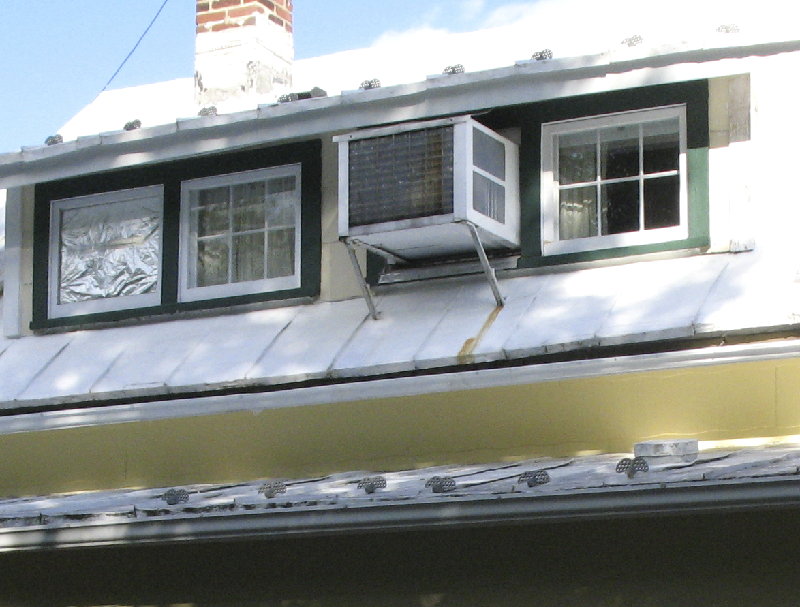
March 2010 - The large window air conditioner shown above was installed
May 1984, in the second floor dormer window, replacing an old 10,000 btu 120v Admiral window unit. The 185 pound Sears 18,700
btu 240 volt window air conditioner did its job well, but not very quietly and certainly not without a lot of electric
consumption. I serviced it every year, including making repairs to the steel bottom pan, which started rusting away, after
about 15 years. As the summer of 2010 approached, it was clear that this old machine might not make it another year, nor was
the racket it was now making going to allow us to put up with the noise for another year.
In fact, the bottom pan broke in half, when the Mitsubishi dealer/installers (2 men) removed
it from the window and placed it in the back of their truck. No doubt that it was time to replace it! Now, I could finally
deal with the dormer window, to get it ready to support the installation of a ductless system... a Mitsubishi MSY system,
model GE12NA which is a 12,000 Btu/h system (capacity range is 3,800-13,600 Btu/h) with a SEER rating of 20.5. Due to the
many improvements we've made to the energy efficiency of the house, a system as large as the 18,000 Btu/h unit being replaced
is not needed.
Info about 'Inverter Compressor' technology and Mini-Split
systems
Here are several links to articles that discuss the benefits
of this technology, used in most split system ductless air conditioning systems... Article 1, Article 2, Article 3 and a .pdf file format article. Lastly, here is an 8 minute video from Mitsubishi, which talks about and shows the benefits of their
Mr. Slim system.
A very recent article asks... Will Minisplits Replace Forced-Air Heating and Cooling Systems?, addresses the questions associated with the new January 2012 Energy Star Version 3 Specs and mandatory commissioning, not
previously required for home HVAC installations. And another recent article... It's Air Conditioning, Not Air Cool-ditioning, talks about systems that deal well with humidity control in humid areas, like our own Virginia location.
If you find additional articles that you consider very informative,
please send me links to them so I can post them here, for others to benefit from.
 The old cabinet will go to the dump, its guts removed by the Mitsubishi
dealer for freon recovery. You can see that this was not a small window air conditioner.
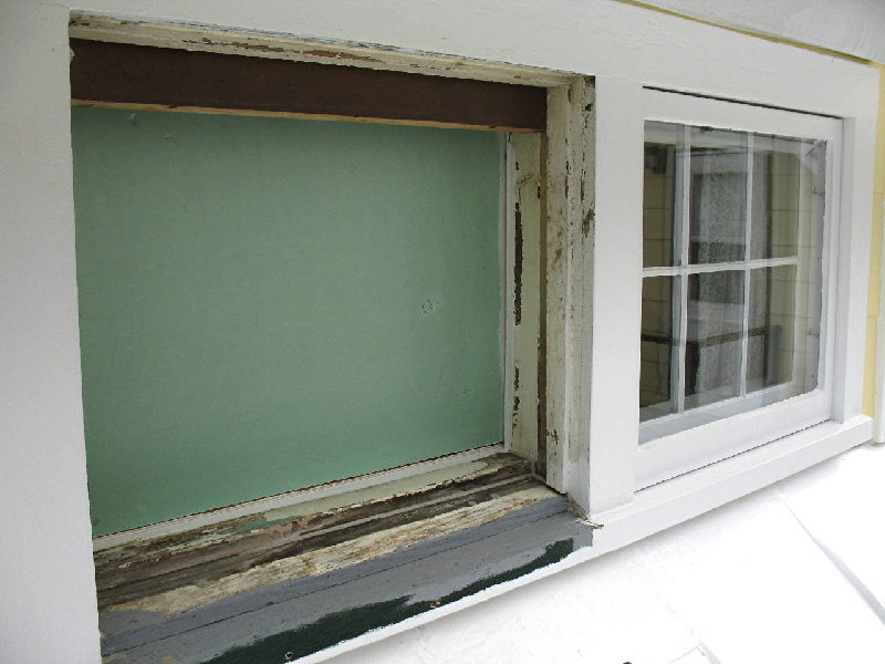 The window frame opening wasn't very bad at all, (thanks to old
growth wood) since we didn't do anything to it at the time we removed a very old 10,000 btu Admiral 120v unit and installed
the new larger capacity 240v Sears unit. The 1 x 2 solid maple piece at the top of the frame helped support the bigger unit,
along with vertical braces below the unit. In this picture, a piece of 1-inch ridged green insulation panel has been placed
on the inside of the window opening, to keep the bugs out, while the exterior window trim is restored and refinished. The original
window sash has been used in the front door, as shown elsewhere on this web site.
The house in 1984 was not very energy efficient... one of the two
attic vents (south side) had been covered over with cement asbestos siding sometime in the late 1950's, preventing any attic
flow-thru ventilation, there was no soffet ventilation, no bathroom ventilation fan, no knee wall insulation in the bedrooms,
very leaky original windows (we could actually see the light weight window curtains move with strong wind gusts outside)
and many air leak areas around the entire house, which is why the 18.7k btu unit was installed to help overcome
the situation. Of course, all of these issues have since been corrected. The upstairs rooms now only needs 12k btu
cooling capacity due to the many energy efficiency improvements we've made since 1984.
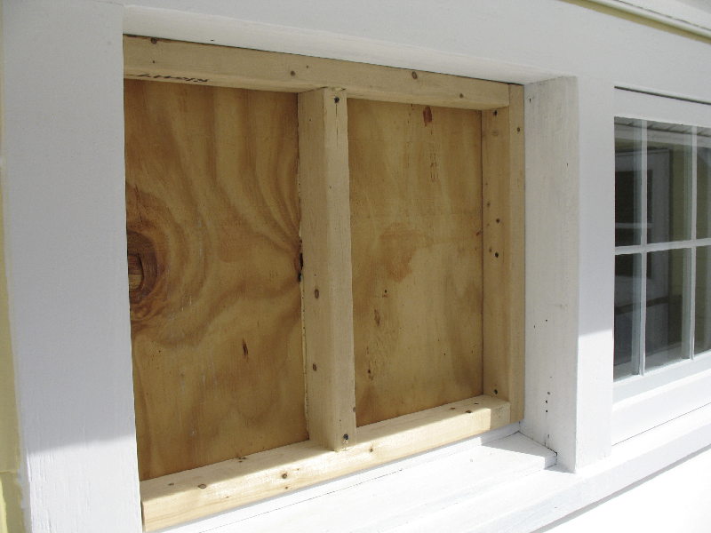 With the old paint scraped and sanded off and a coat of primer ready
for caulking, the window was simply enclosed using 3/4-inch exterior plywood and framed with 2 x 3 material, using screws
so that the frame can be removed easily, if desired by a future owner. The vertical center support is glued to the
plywood, to provide a solid mounting for the new air handler and prevent potential vibration noise. Double foil faced 2-inch
R-16 polyisocyanurate foam board is used to insulate the frame, seen below.
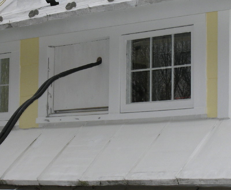 The plumbing lines and a 14-3 120v supply line from the outside
compressor run into the house through a 3-inch hole in the window box. The outside exterior plywood cover has been attached
and primed... the gray spots are caulking, waiting for the second coat of primer and two finish paint coats.
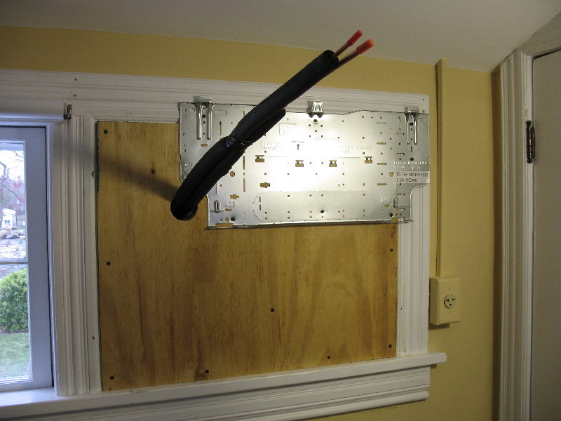 The hole position for the plumbing and electrical lines is specified
by the air handler mounting bracket, for both left and right side plumbing access. The 14-3 electrical line is not yet in,
which provides power from the outside compressor unit. The three tabs at the top of the mounting bracket is what the 23 pound
inside unit hangs from, secured at the bottom lip. The old original 20 amp 240v outlet for the window air conditioner can
be seen in the right hand corner.
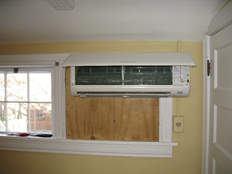 With the inside air handler mounted, this is its cover showing where
the air filters are located. The small panel on the right is where the 14-3 cable is connected, in the close-up below. In
looking at the door on the right and its hinge placement, if you're thinking it will hit the air handler, you're right. It
will be moved to the inside of its frame and open into the room.
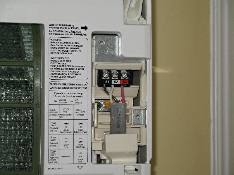 I did all of the electrical wiring for both systems, running two
240v 15 amp circuits to the outside compressors and the 120v lines from the compressors back to the air handlers. Getting
the wire into the air handler cabinet and through the back and up into the area where the connections are made is very
tight. Further, the terminals are not positioned for todays current flat 14-3 cable, but were meant for round 14-3 cable.
I was unable to locate any round 14-3 exterior grade cable!
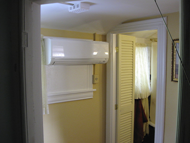
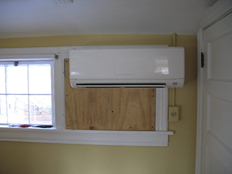 This is a front view of the cabinet with its front access panel
closed. Below are pictures of the two rooms it will blow into. One slightly to the left of the cabinet, the other directly
in front of it. There are two sets of air direction vanes in the air handler, so air flow can be directed into each room.
In the pictures below, you can see the painting and bathroom door change has been completed. We didn't move the original solid
door, but decided to install a wooden bi-fold louver door, to assist in cooling the bathroom when the door is closed. This
has turned out to be a very good door solution, allowing both privacy and ventilation. Note that the louver openings are
positioned as they would be for an external shutter when closed, facing down.
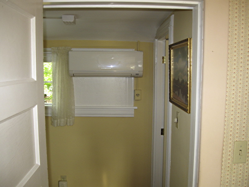
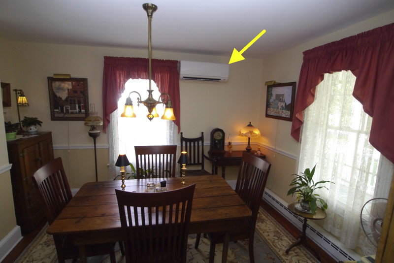 Looking into the dining room from the living room, you can see the
other air handler at the upper right corner of the window. It is also a Mitsubishi MSY system, model GE15NA which is a 14,000
Btu/h system (capacity range is 3,100-18,200 Btu/h) with a SEER rating of 21. It replaces a 14,000 btu 120v window air conditioner
that sat in the window next to the new air handler. During the summer, you had to shut the window unit off during meals, because
of its direct air flow across the table. Not a good idea to have friends over for a meal, on a hot summer day!
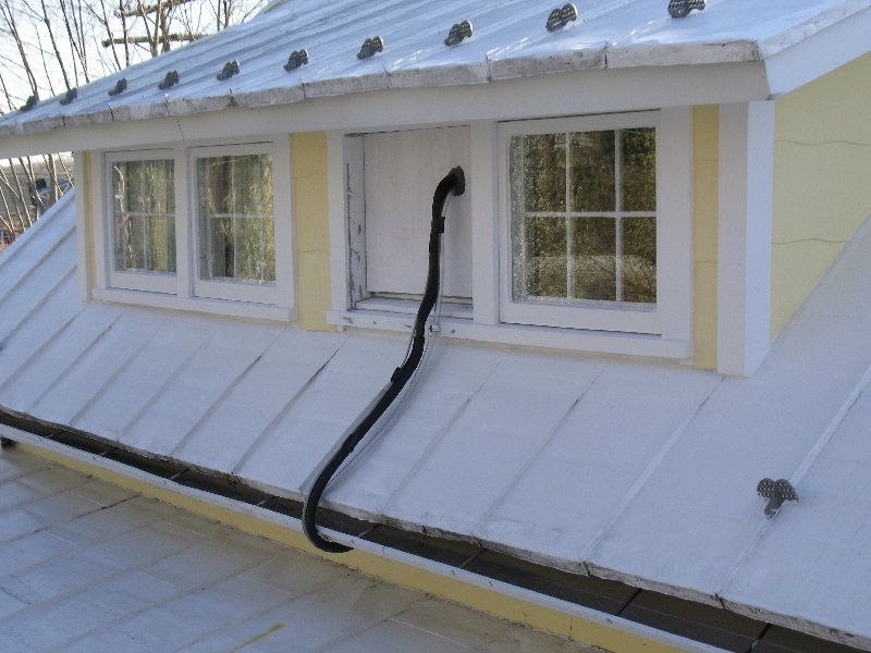 Work in progress, with the insulated plumbing shown going into the
upstairs window cover, to connect to the upstairs interior unit.
Update July 2010-
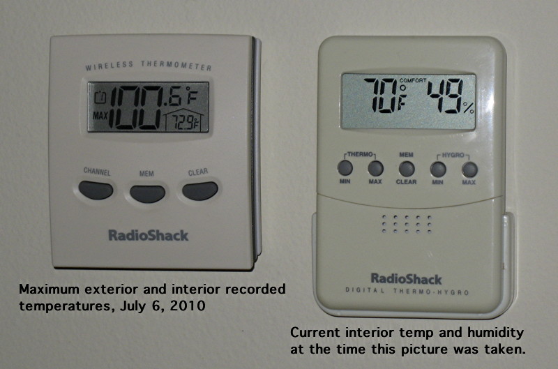
During our very hot 100F temps during early July, I noted that the
cooled air temp at the face of the outlet vents (measured with a Fluke 8060A and thermal probe, 1% accurate) of the upstairs
unit was 4F-6F degrees warmer, then the downstairs unit, 46-48F versus 42F at maximum cooling and the same differential at
lower cooling levels. (IE: 56-58F versus 52F) Upon inspecting the black insulated plumbing, where it comes out from beneath
the roof overhang and up to the new window cover, I found that the black plumbing insullation was very hot to the touch, because it
is on the west side of the house with the afternoon sun beating down on it, versus the downstairs unit plumbing which
is on the north side and no sun exposure.
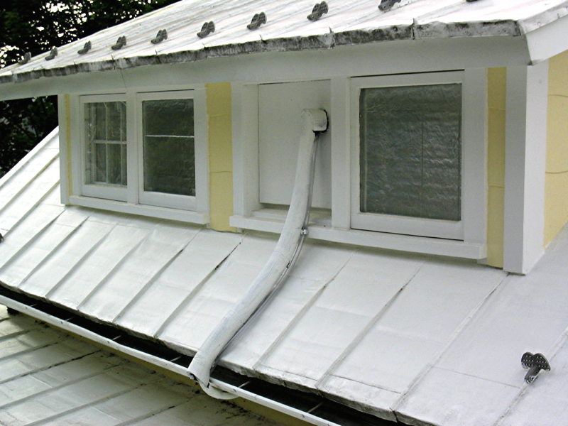
I decided to try additional insulation on the plumbing to see if that might help. I added a
larger diameter insulating pipe cover, painting it white to help reflect the sun light. Fortunately, this did the trick! Had
it not, my next step would have been to have the charge level checked, because this unit is a much greater distance from the
compressor, then the other unit.
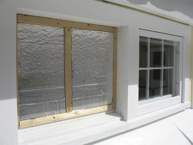
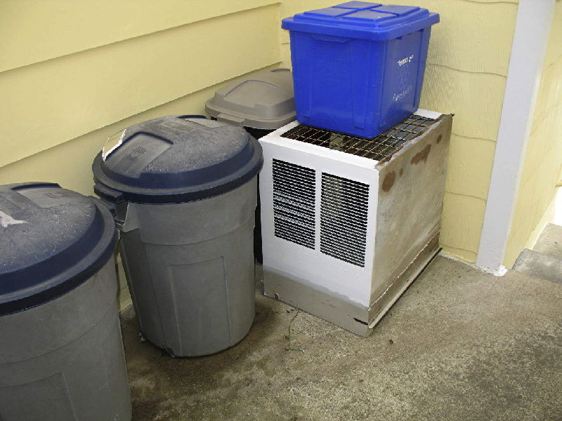
The picture above shows the original window air conditioner in the
dining room north window, covered during the winter. The air conditioner sits in a frame built to support it, so that the
100+ year old window is not used to support it, as is typical of window air conditioner units hung out of windows. The air
conditioner's inexpensive folding vinyl side curtains were removed and replaced with 2-inch double foil faced R16 foam panels,
sealed in the frame that sits in the window opening, making it weather tight. If you're still using window air conditioners,
give some thought to building a frame with foam side panels, which greatly reduces heat penetration and allows the unit to
stay in the windows during the winter, if necessary.
The aluminum triple-track storm windows are still in place on all
four of these north side windows, the second floor windows have been rebuilt, but work has not yet started on the first floor windows
at the time this picture was taken.
Note the addition of aluminum vent panels for the attic and the knee wall above the porch ceiling,
which are at both ends of the house. These areas previously had no ventilation!
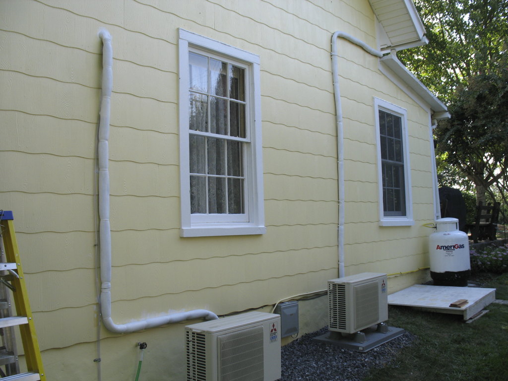
The pictures below show the split-system installation work
in progress... all the plumbing and wiring that goes into the house to the interior air handlers. The
plumbing with its insulation wrap, compressor platforms, disconnect box, etc., ready for the exterior compressor units to
be placed and connected.
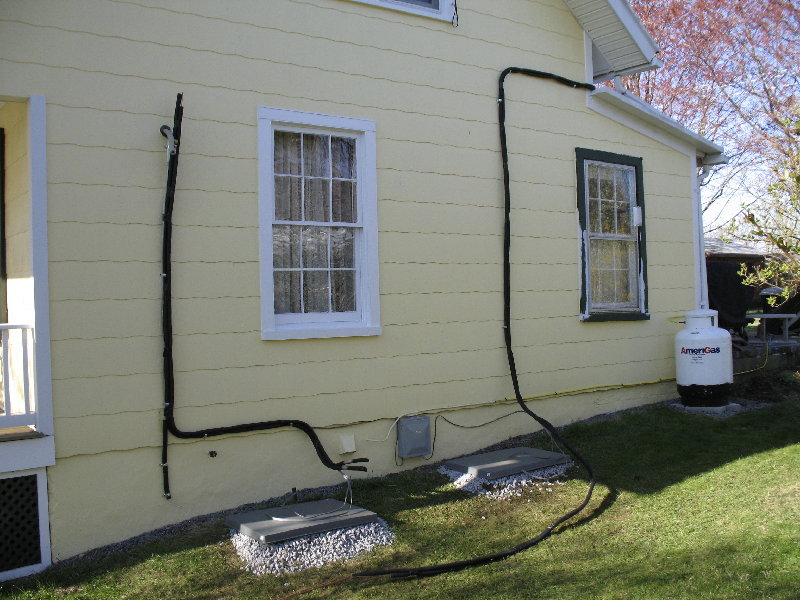 Fortunately, the compressor units can be located along
the north wall of the house, taking advantage of the shade 90% of the summer day, as shown above where the mounting pads have
been positioned. The white window directly above the pads is where the second window air conditioner (14,000 btu) was located
for cooling the first floor.
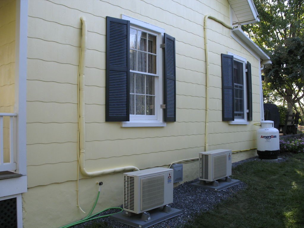
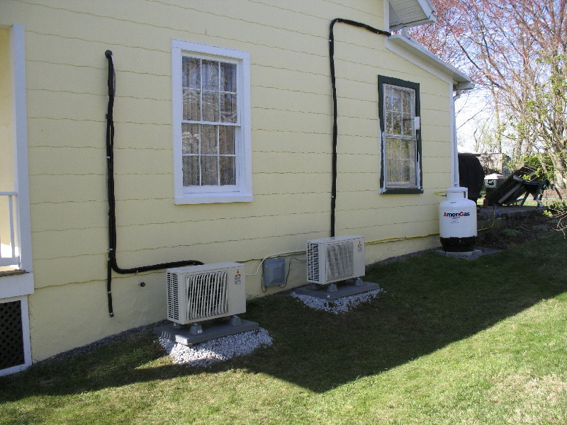 Everything in place, connected and running. The green trimmed window
on the right next to the propane tank, is the last window (#20) in the house to be restored. Restoration of all the windows started in 2000 and has been ongoing since then, along
with the other projects such as these new Mitsubishi ductless systems.
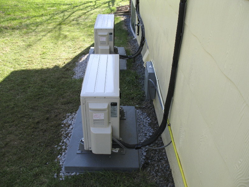 While the compressor units can sit much closer to the house wall
(minimum 4-inches) this position is considered optimum for ideal cooling and servicing. Yes, the plumbing's ugly black foam
insulation will be covered with a vinyl plastic cover, which will be painted the same color as the house. When completed,
I will post additional photos, below.
Update July 7, 2010
The performance of the Mitsubishi systems have been excellent, in terms of keeping the
house very cool and their very quiet operation, during our past 97+F (36+C) temps and 85% - 100% humidity days this past June
and now our very hot early July temps, with very sunny days producing lots of radiant heating. I am still tinkering
with their many settings inorder to determine which modes of operation are the best, given our configuration. I will post
settings I've adopted, once I have enough experience with those that I am trying, along with the KW/h use that I am recording,
to see what energy savings are actually being accomplished, versus our earlier window units KW/h costs.
At the moment, the 'Dry' mode, which calls for cooling inorder to maintain a humidity level
of around 48% (measured), seems to be a very good setting at 'Medium' fan speed. It also maintains the temperature at 72-74F,
which is not adjustable in 'Dry' mode. The removal of humidity is very rapid, compared to our earlier window units performance.
Update Sept. 29, 2010 What Level of Savings and Performance Have We Actually
Obtained?
A short report showing the cost savings of the Mitsubishi systems versus the old window air conditioners and their associated energy costs,
during the months of July, August and September 2008, 2009 and 2010.
The August 30, 2010 electric bill was $94.14 and we used 216kWh less then last August (882kWh
vs. 1098kWh), which was also as hot, but our window air conditioners were set at 78F, not the much cooler 72F we used
this August. Excellent performance and savings, in our opinion and experience.
Update Oct. 15, 2010
(edited to address reader questions)
With the very hot temps now gone, work begins again on doing something about the ugly black
pipe insulation on the outside north wall, for the Mitsubishi units. While I had tried using plastic drain plumbing pipe,
the labor involved was not going to be small and I had some concerns about covering the large radius bends, with the configuration
of typical drain pipe elbows, with their small radius bends. As luck would have it, I learned of a product made specifically
for hard to prime surfaces, called STIX, made by insl-x and used by local old time painters for painting very difficult surfaces of various materials, by using
this primer. So, I decided to give it a try, using it to primer the foam based pipe insulation, added to my existing
Mitsubishi plumbing. 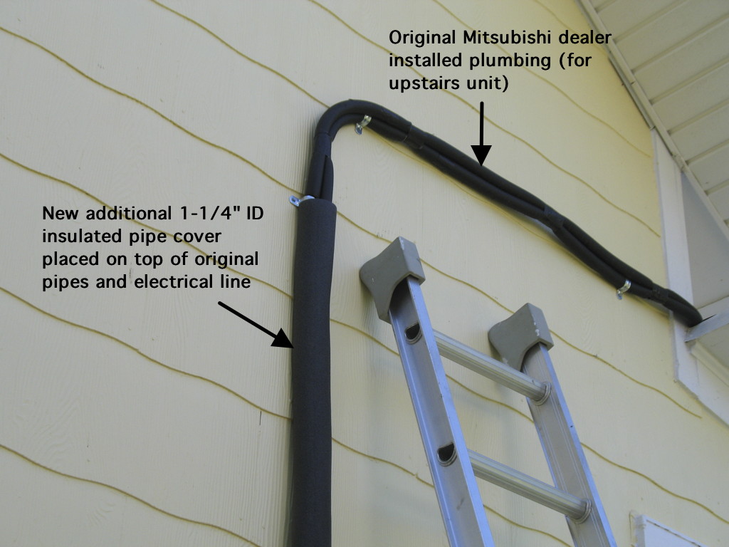 The additional pipe insulation will be held in place with cable
ties, which are UV resistant... not easy to find but your better electrical supplier will have them.
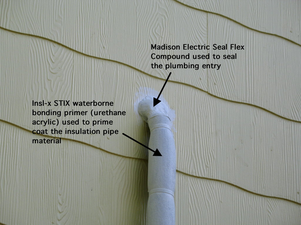
 I used Madison Electric Seal Flex Compound, to seal and form a cap shape for the plumbing coming out of the wall for the downstairs unit. A coat of STIX has been applied
to the insulation pipe and was allowed to cure for 24 hours, before painting. Again, advice from experienced painters and
users of this product, strongly suggested not to paint it too soon. Give it a full day of good drying weather so that it can
do its job when you paint it, using acrylic paint only, to allow typical dimensional temperature changes without excessive
cracking.
 The rest of the pictures show the end result. Took about 8 hours of labor to install the insulation,
prime it with two coats and paint it with two coats and cost $33.61 for all the materials. If it holds up well, it'll be a
bleeding bargin compared to the Mitsubishi cover system installation for the plumbing, which I was quoted $900 installed,
$450 for each system. We'll see how long it actually lasts and when it has to be recoated.
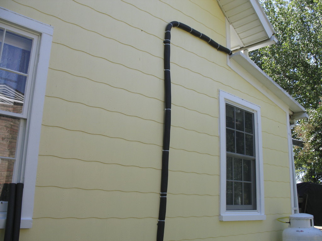
 Finished with the house color paint and both of the vinyl shutter
pairs are now mounted. From the street, as shown below, the air conditioning plumbing is now much less apparent and the
look of the vinyl shutters mounting treatment is quite realistic.
What appears to be an additional benefit, is that the outlet air
temperature of the upstairs interior unit, which has the much longer plumbing run, is now measuring 2-3 degrees colder (Fluke
8060A Digital 1% accuracy temp probe) and the compressor fan on the outside unit is running at the slower speed, for
longer periods, without increasing its speed as often. It was another 97F degrees day, after I had completed the painting
of the additional foam insulation cover. Is this additional foam covering what reduced the cold air output temperature
by the several degrees? Seems possible, but in any case it's there and we'll certainly use it.
 Why the Mitsubishi ductless system?
I posted the question about which brand ductless system to purchase, on all the major old house
forums on the Internet and I had a very good response level. The majority indicated that the Mitsubishi system, while typically
more expensive, was considered the best quality and had a very good track record with owners who indicated they had 3 - 5
years of experience with the product. Quite a few respondents from Japan and Australia as well as the south east U.S., many
from Georgia. Most all were installed in old homes, except some in Asia and Australia.
My initial opinion of this Mitsubishi ductless system?
Amazingly quiet, not only the inside air handler, but also its outside compressor and
fan. You have to actually experience them, since there is no way to describe what I mean by saying "quiet". I'll be monitoring
them later this week, as the temperatures get into the 80's and the systems will have to do a bit more work. I have both
direct and indirect measuring professional sound level meters and I can provide A-weighted noise level readings to those
who will understand them. Email me.
How was the Mitsubishi dealer to work with?
Overal, very good, once we got past some initial misunderstandings and clarified who was responsible
for what. I hope to follow-up with them to make some suggestions about working with an old house DIY'er, such as myself, when
their time permits a meeting. But, it's already becoming their busy time of the year with summer coming on.
The two installers were great guys, very savvy and pleasant to work with. Plus, I ask a lot
of questions so I can learn things from people who make their living actually doing these things and they had no problems
with this.
Contact me for additional info and who my Mitsubishi dealer was.
Back to the HOME page
Update November 13, 2012
On a related matter, I have been looking at the effect that high humidity has had on older homes,
as some of my neighbors leave their windows open to draw in cool evening and early morning air, while attempting to keep their
electric bill at a minimum. I also looked at several foreclosure properties, that had left a window or two partially open.
The problem with this is that they are filling their house with high levels of humidity (70% to
90%) and then figuring the air conditioner(s) will deal with this when turned on later in the day. This whole approach
is wrong! Please read the articles at the following links, if you are doing the same thing.
September 10, 2013 -
I am still attempting to find a source for the special vacuum cleaner hose and brush attachments kit (MAC-093SS-E) that Mitsubishi
sells, to assist in cleaning the rotary fan in the inside unit, which becomes clogged with dirt and particles after some period
of use. At the moment, this kit is only available from Mitsubishi sources in Europe, who will not ship it to the U.S. I
contacted Mitsubishi U.S.A. to have them help me find a U.S. source for this cleaning kit product. The product is shown here. Mitsubishi has not responded with a local source and continues to state that their 'authorized dealers' are supposed to
provide the recommended cleaning services. This simply is not true, as I have not been able to locate a 'dealer' who provides
cleaning services that involves any of the processes shown below at the Youtube links! I have to do it myself, or suffer major
cooling efficiency loss in both my units. This is quality service? Here are some links to various methods shown on youtube, used to clean
the rotary fan in the split system units. They range from simple vacuum cleaner use to low pressure water spray
washing. None of which are offered in my area... only installation of the system and only a few offer electrical connection,
which you have to obtain or supply. Today, the needed
Mitsubishi product arrived at our house from a fellow BMW E28 owner in New Zealand who offered to help me obtain
the Mitsubishi Vacuum Cleaner Attachment Kit last month. Now I can clean the fan in these units easily and not take hours
to accomplish the task! Thank you my New Zealand friend! And shame on you, Mitsubishi, for making the whole maintenance process
a nightmare for us DIY old home owners who invested no small amount of money to buy your products!
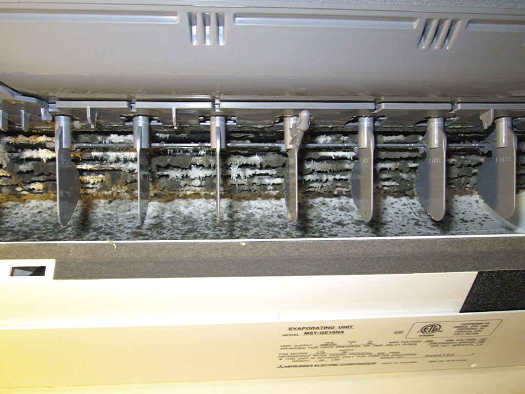
Close-up looking into air outlet of the Mitsubishi interior air handler
unit. The vertical air direction blades are in place in this picture, but can be removed. However, you can see the dirt that
has collected on the fins of the rotary/barrel fan blades, greatly reducing the amount of air that the fan can now produce.
I estimate that at the highest fan speed setting of #4, its volume of air flow is only equal to the lowest #1 setting! It's
hard to see in this view just how hard it is to get to the fan and clean the blades. A new picture will be posted once the
vacuum cleaner attachment arrives and I can show how it is used to access the rotary fan. The needed
Mitsubishi vacuum cleaner attachment kit arrived September 10, 2013 from New Zealand and will be used at the end of our cooling
season, with pictures posted then. This
picture was taken at the beginning of the third cooling season in 2012, after operating during 2010 and 2011 and noticing
that the both units had poor air flow, when I examined their operation in 2012. It took me the better part of 4
hours each to clean these units, due to the extremely tight space and lack of proper vacuum cleaner attachments to fit. The
video links above will show you just how tight the working space is. The owners manual says nothing about this area being
cleaned and only talks about cleaning the removable filters just above this vent area shown in this picture. They were cleaned
EVERY TWO WEEKS, with out fail, but never showed any major dirt collection, like the spiral fans shows. I am very disappointed in Mitsubishi's position that they do not
deal directly with the end user, only their dealers, many (four that I talked to) who do not actually provide a cleaning service
and only partial installation as they also don't do the necessary electrical work and certainly don't supply the
vacuum cleaner attachments that would greatly assist the owner with DIY maintenance... a task old home owners are frequently
involved with! It's a great product, but make sure you are talking to a dealer who will actually deliver a 'turn-key'
installation if you need such. And certainly a cleaning service after their or your system(s) installation is complete!  |
||||
|
|
|
|
--
|