Maintenance tips, comments and links about
performing various types of maintenance.
This page last updated July 5, 2009
Replacing the subframe bushings, using
the technique I prefer.
This article and pictures were
created by Keith, using a technique I have also used, involving a tool available from ZDMAK. Since I did not document my earlier work with this tool, I asked Keith if I could publish
his work, for the benefit of other BMW owners who visit this web site. Here is his article. Thanks, Keith. Using this same
type of tool was also covered earlier this year at MyE28.com in this thread. This is the only process discussion that talks about the "push rod" R&R, but none of the discussions talk about bolt
tightening torque values!
Update July 5, 2009
The New Jersey Chapter BMW CCA Bulletin has an article by Vic Lucariello in Philes'
Forum, about removing a broken inner sleeve in a rear bushing on an E30, which would also apply to the E28. The page
in .pdf format is available here.
Keith's input for this web page is as follows...
The subframe bushings on the E23, E24 (E28-based)
and E28 are all the same and connect the subframe with the attached trailing arms and differential to the body of the car.
To limit noise, vibration and harshness these bushings are rubber coated and consist of an outer steel cylinder and two 25mm
x 50mm (1" x 2") rubber connections to an inner steel cylinder. The failure mode of these bushings is the wear and cracking
of the two rubber connections. The symptoms of less than new bushings are not really noticeable, but as the connections
rip completely, the car may tend to steer a few degrees by itself from the rear. This is an odd feeling as the car requires
a quick bit of steering correction while going staight. This is not what I would call a major steering influence, causing
the car to abruptly change direction, but a couple degrees of steering influence is very disconcerting in a car with BMW driving
dynamics. This effect is different from the lack of rear firmness in transitions when the rear pitman arms (dog bones) are
bad.
|
| - CLICK ON THE PICTURE TO ENLARGE IT - |
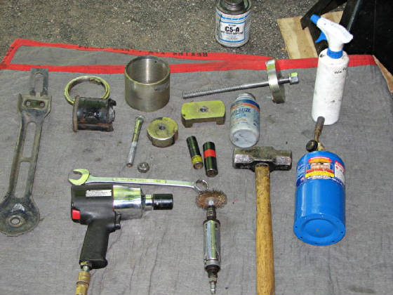
These are the items used for this procedure.
They include, starting at the bottom left, an air impact gun, the push rod from the car already removed, the alignment ring
from the tool above the old bushing, the receiving cup for the bushing, above the stud and nut and the other parts of the
tool, a squirt bottle with water plus 3 drops of liquid soap, anti-seize, sockets, a propane torch, short sledge hammer and
a die grinder with wire brush.
The subframe is held to the car through these bushings
by 9mm x ~130mm studs. These studs have a splined shoulder that is pressed into an opening in the floor of the car under
the rear seat and must be removed to use either of the BMW tools to replace the bushings. The use of these tools do not
require the removal of the subframe from the car.
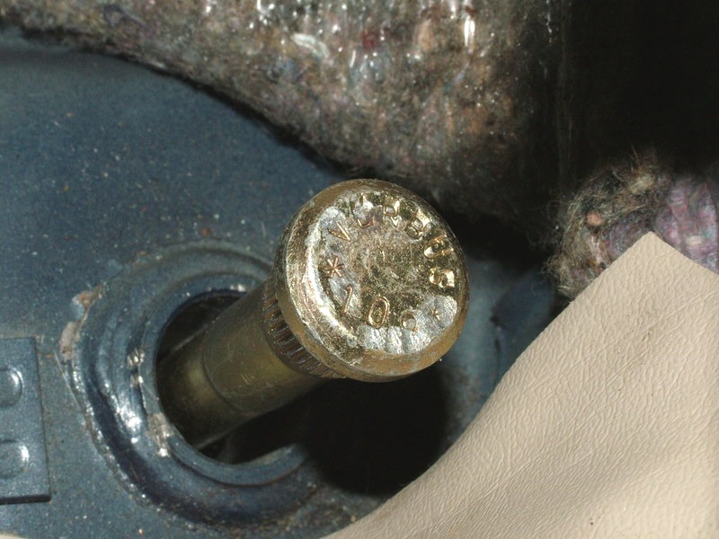
|
| The bushing stud. |
|
| Bushing stud removed from its location in the floor. |
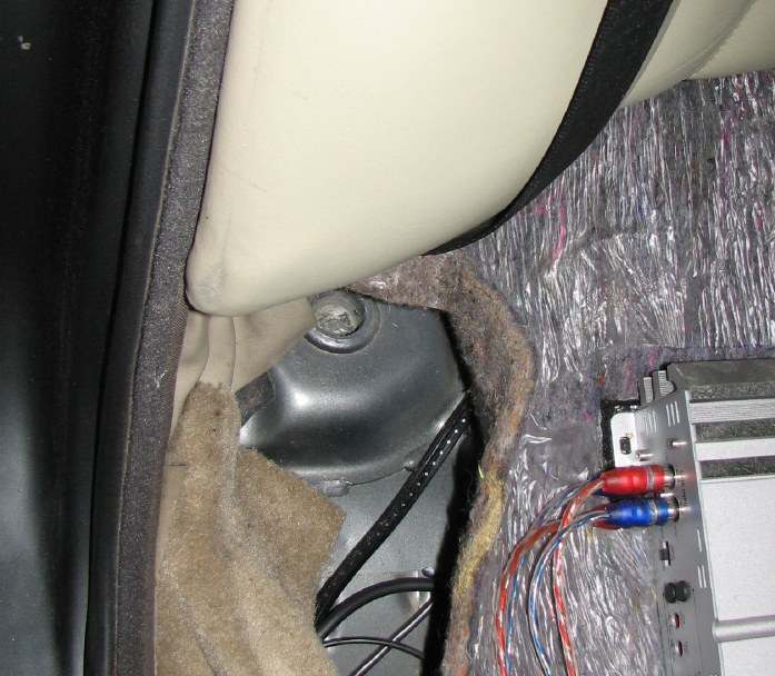
Remove the back seat bottom to access the subframe
retaining studs. These are in the recess right at the bottom of the seat back. It may be helpful to use your favorite
penetrant (Liquid Wrench, PB Blaster or whatever) a week before doing this job. Do this by putting a good amount in the
recess and allow it to work. This may make removing the studs easier.
|
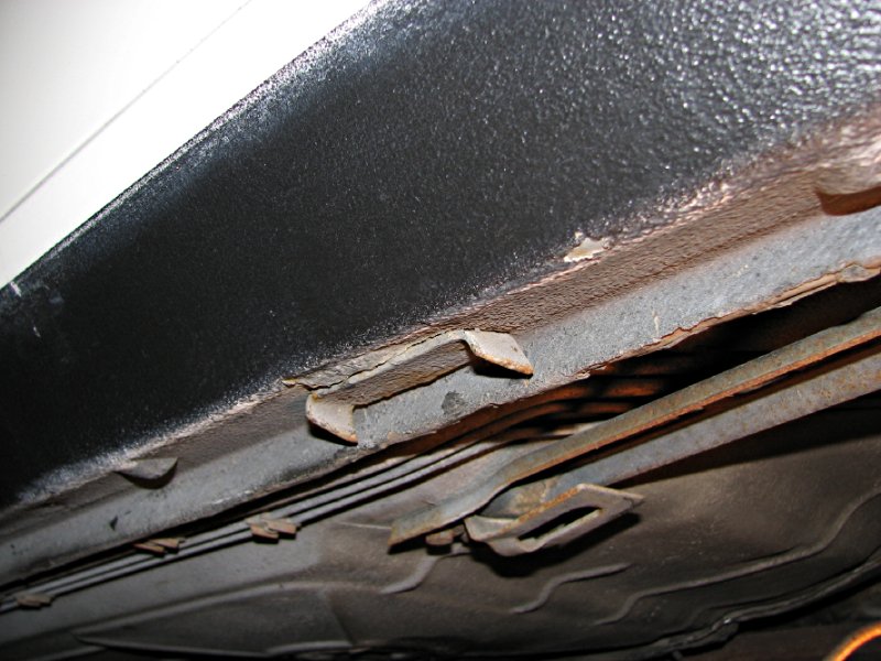
| Jacking/lifting point bracket on the bottom of the E28 rocker panels. |
This procedure requires working under the rear of
the car with the subframe able to be dropped a few inches so the subframe can not be used to support the vehicle with jack
stands after jacking the car. The body of the car must be supported so the best spot to do this is the BMW provided jacking
points on the vehicle. Jack up the car, position the jack stands and verify the car is correctly lifted and safe to work
on. Remove the rear wheels for better access.
With the car supported, put the jack under the subframe/differential
to support it while the subframe is unbolted from the car. Remove the push rods from the car. These are the two
metal plates attached to the subframe studs and are held in place with two 13mm bolts into the body and the 22mm nut on the
bottom of the stud. With this part removed, the stud removal is done in a number of differnt ways. If the car
is high enough, you can lay down to swing the hammer. If not, then swinging from a kneeling position with a cautiously
short backswing (try it you will know why) will allow some force to be used to remove the stud. If the car is on a lift
and a high quality air hammer is available this may be used to remove the stud. I do not have an adequate air hammer
so I used the 3# sledge in the picture to remove the stud. To protect the stud, rethread the nut onto the stud until it is
flush with the stud. I turned the nut over as it has a flat bottom and provided a larger hitting surface. This
may take a few hits with the hammer, it may take a lot, but it MUST come out. It is also recommended to have a replacement
nut on hand, while others recommend having replacement studs available also. Use the same nut on both sides if it survives
the removal of the first stud. When the stud pops loose, remove the nut and then remove the stud from the car.
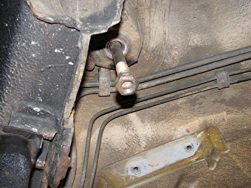
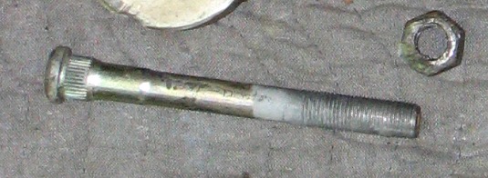
|
| Stud with the nut partially threaded to protect the stud during hammer strikes |
In the above picture, the subframe has been removed
for other reasons, which affords a better view of the stud and its location.
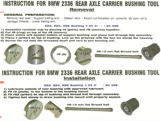
The BMW tool can now be set up to remove the bushing.
This is detailed in the instructions below.
|
| - CLICK ON THE PICTURE TO ENLARGE IT - |
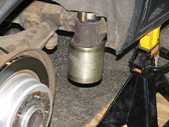
The bushing removal tool consists of the through bolt,
an upper threaded piece that will fit the subframe and pull the bushing as the rod is threaded into it, an upper alignment
ring that fits on the bottom of the subframe bushing mount, a bushing receiving cylinder and the lower alignment disc that
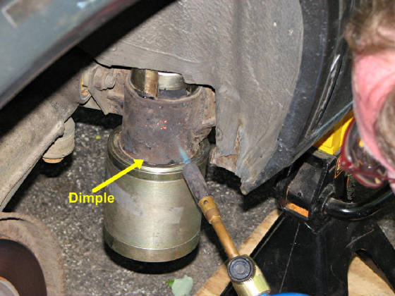
will support the force of removal. The top threaded piece has notches that must be aligned with the dimples in the subframe
to allow it to pull the bushing past these. It can be seen properly aligned in the picture with the torch heating the
bushing. The tool is available from this source.
|
| - CLICK ON THE PICTURE TO ENLARGE IT - |
|
| - CLICK ON THE PICTURE TO ENLARGE IT - |
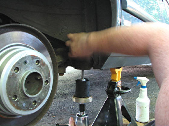
To make the bushing come out more easily, heat the
subframe to melt/burn the rubber coating of the bushing. This does not take long, a few minutes or so as only a small
area that puts the heat on the bushing and not of the subframe joints and connections.
|
| - CLICK ON THE PICTURE TO ENLARGE IT - |
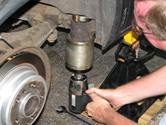
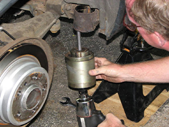
After heating, remove the bushing by screwing in the
threaded rod. Make sure the threaded rod is lubricated properly with anti-sieze. This BMW tool allows the use of air
tools which the other BMW too did not allow. I prefer this tool for more than that reason. This One is more stable
and seems stronger.
|
| - CLICK ON THE PICTURE TO ENLARGE IT - |
The bushing will come out with the tool as it is released from the subframe. The opening in the subframe can now be
wire brushed to clean it and allow an easier install of the new bushing.
|
| - CLICK ON THE PICTURE TO ENLARGE IT - |
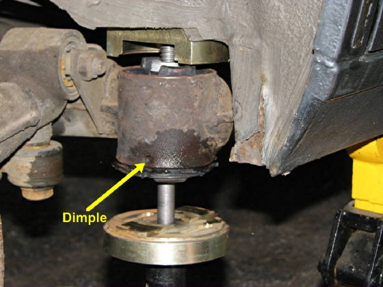
The bushing installation tool consists of a top threaded
piece, the threaded rod and a lower pushing plate. The top piece has a lip that sits on top of the subframe and has cutouts
to receive the bushing rubber protrusions. The cutout and lip are aligned and the through bolt with the bushing and the
pushing plate are installed and tightened by hand until resistance is felt. The bushing needs to be aligned at this time
to put the indentation on the side of the bushing in line with the dimples on the subframe which can be seen on the lower
edge of the subframe where the area has been wetted. After aligning the bushing and tightening the through bolt, spray
the bushing with special BMW assembly lubricant, or just use some water with a very small amount of dish washing liquid in
it. About 3 drops per quart of water is fine. Do not use a lubricant that will not evaporate or disappear in some other
way as this could allow the bushing to back out later. Now install the bushing using tools. Make sure the bushing
goes all the way in. More power may be necessary.
Reinstall the stud with a new self locking nut, and tighten to 140Nm (103 lb-ft).
Replace the stud if the threads were damaged during the removal process.
|
| - CLICK ON THE PICTURE TO ENLARGE IT - |
|
| - CLICK ON THE PICTURE TO ENLARGE IT - |
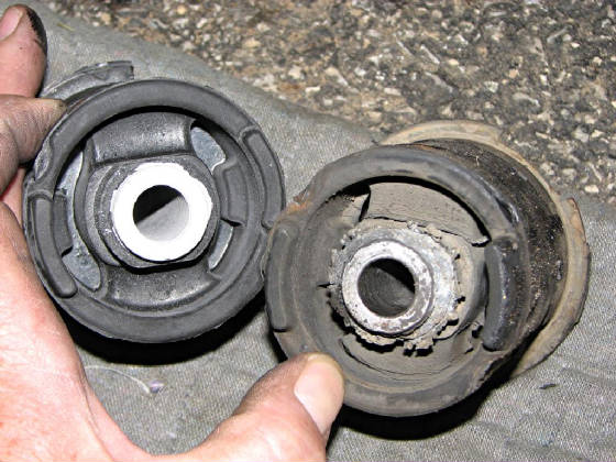
The old bushing shows the deterioration that happens
over twenty years or daily driver use. The two 1" wide rubber ribs between the inner and outer sleeves are cracked. These
cracks continue until the two sleeves are separated.
The
new bushing is the standard new bushing, not the polyurethane filled, road noise inducing bushing some want to modify before
installation. It is also not a picture of the newer Meyle reinforced bushing which I have not seen. The originals
lasted 20 years, no reason to think a new set of standard bushings won't do the same.
Keith
__________________________________________________
There are two other bushing
replacement techniques that have been published by other people, one is what I call the "Saws-All" (link broken 6/15/11) technique, since it literally involves cutting the bushings to get
them out. No thank you... the "Pros" that invested time to train me decades ago would have a fit if I involved this cave
man technique. However, if you have absolutely no other resources available, you've gotta do what you can to fix it.
The other uses the BMW "KUKKO" (link updated 6/15/11) puller tool, which I have watched being used,
but I have not actually used it myself.
-Rod
|