

Waaaaaaaaaaa!
-
Kyle in NO
- Posts: 17638
- Joined: Feb 12, 2006
- Location: Nasty Orleans------> Batten-Rooehjch------>More Souther LA
Can't you faggots shut the fuck up already?
Last edited by Kyle in NO on Sep 04, 2011 5:52 PM, edited 2 times in total.
-
Bill in MN
- Posts: 1718
- Joined: Feb 12, 2006
- Location: The Boonies, Mn
- Contact:
Duke, got some questions for you here:
Stipulated that the M30 block layout was never designed for FI, how does the water passage configuration compare to the M106 block that BMW used for the 745? Now it's my understanding that the 745 boost levels were kept fairly low . . . around 8 psi IIRC. If that's the case, it would tend to support the "use low boost" theory.
Now the next question: in the late '70s, BMW did some outrageous things in Formula 1. The engines they used at the time were 1.5 liter blocks known as the M12. These were jacked up to around 60 psi (4.0 bar). Running on nearly straight toluol, they produced around 1500 fwp.
It's my understanding that the M12 block was essentially the same as the M10 used in the 2002, but with the bores sleeved down to help get from 2 liters to 1.5. From what photos I've seen of these blocks, the water gallery layout isn't much different than an M30 . . .think of the block as an M30 with 2 cylinders cut off.
So the question: is the cylinder sleeving the engineering change that made the blocks survive 60 psi, or is it something else?
Looking at the M30 vs. the 2JZ-GTE, the M30 water gallery layout does leave something to be desired; however the location of the head studs is more or less the same, with 4 studs surrounding each hole. With proper hole preparation and using studs designed to support the axial stresses, I would think that both motors would have comparable strength.
What this leads me to think about is (a) are there differences in the internal design of the 2JZ-GTE which make it stiffer, or (b) are different assembly techniques used to address the higher Brake Mean Effective Pressures which come with FI?
As far as the latter is concerned, Paul Burke recently posted some YouTube videos which illustrated some of the meticulous assembly machining which went into the build on some very high HP S54 blocks. Notably, these blocks did not use O-rings as part of the assembly. This would tend to support the concept of the head gasket being the "fuse" in the design.
Another thing that was very apparent in the build videos was the emphasis on maintaining ultra-close machining tolerances. Without rubbing salt in anyone's wounds, some of the reliability issues related to 1-bar + boost in M30s may have to do with the quality of the machining and the RA levels on both block deck and the head mating surface.
ISTR that T_C_D had built a number of M30s which were working with around 18 psi or so. Don't recall if he was experiencing HG or other failures related to high cylinder operating pressures.
In my own experience, during the Lucifer's Hammer build, we did see failure of a stock BMW S38B38 gasket at around 12 to 13 psi. This was using stock BMW head bolts (not torque-to-yield). The B38 gasket was used to accommodate the larger cylinder bore. With this failure, we went to using a Cometic MLS gasket and ARP head studs; no problems since, with boost levels at 15 psi.
Thoughts?
Stipulated that the M30 block layout was never designed for FI, how does the water passage configuration compare to the M106 block that BMW used for the 745? Now it's my understanding that the 745 boost levels were kept fairly low . . . around 8 psi IIRC. If that's the case, it would tend to support the "use low boost" theory.
Now the next question: in the late '70s, BMW did some outrageous things in Formula 1. The engines they used at the time were 1.5 liter blocks known as the M12. These were jacked up to around 60 psi (4.0 bar). Running on nearly straight toluol, they produced around 1500 fwp.
It's my understanding that the M12 block was essentially the same as the M10 used in the 2002, but with the bores sleeved down to help get from 2 liters to 1.5. From what photos I've seen of these blocks, the water gallery layout isn't much different than an M30 . . .think of the block as an M30 with 2 cylinders cut off.
So the question: is the cylinder sleeving the engineering change that made the blocks survive 60 psi, or is it something else?
Looking at the M30 vs. the 2JZ-GTE, the M30 water gallery layout does leave something to be desired; however the location of the head studs is more or less the same, with 4 studs surrounding each hole. With proper hole preparation and using studs designed to support the axial stresses, I would think that both motors would have comparable strength.
What this leads me to think about is (a) are there differences in the internal design of the 2JZ-GTE which make it stiffer, or (b) are different assembly techniques used to address the higher Brake Mean Effective Pressures which come with FI?
As far as the latter is concerned, Paul Burke recently posted some YouTube videos which illustrated some of the meticulous assembly machining which went into the build on some very high HP S54 blocks. Notably, these blocks did not use O-rings as part of the assembly. This would tend to support the concept of the head gasket being the "fuse" in the design.
Another thing that was very apparent in the build videos was the emphasis on maintaining ultra-close machining tolerances. Without rubbing salt in anyone's wounds, some of the reliability issues related to 1-bar + boost in M30s may have to do with the quality of the machining and the RA levels on both block deck and the head mating surface.
ISTR that T_C_D had built a number of M30s which were working with around 18 psi or so. Don't recall if he was experiencing HG or other failures related to high cylinder operating pressures.
In my own experience, during the Lucifer's Hammer build, we did see failure of a stock BMW S38B38 gasket at around 12 to 13 psi. This was using stock BMW head bolts (not torque-to-yield). The B38 gasket was used to accommodate the larger cylinder bore. With this failure, we went to using a Cometic MLS gasket and ARP head studs; no problems since, with boost levels at 15 psi.
Thoughts?
Fixed. Poor choice of words. I should have said your "experiences".Duke wrote:Get it right Todd..............your personal failures, funded by me on my car.T_C_D wrote:Your personal failures
Last edited by T_C_D on Sep 04, 2011 6:37 PM, edited 1 time in total.
Chris, the water passages in the S38B35 block are approximately half again the size of those in the M30. Same locations, but much larger openings. I can email you pics in case you're interested. I think the s38's water pump has a different layout than the M30--fewer vanes on the impeller which reduces possible cavitation at higher speeds.wkohler wrote:How did they address coolant flow in the S38 at high rpm? Could that be adapted to an M30 application?
HTH.
And Duke, nobody's pimping you about your build. You and I have had a lot of emails on this topic. OK, bro?
Last edited by Ken H. on Sep 04, 2011 6:59 PM, edited 1 time in total.
-
Bill in MN
- Posts: 1718
- Joined: Feb 12, 2006
- Location: The Boonies, Mn
- Contact:
I can understand the logic of having coolant coming into the head initially on the exhaust side, but will someone please explain why the coolant openings in the HG are significantly smaller than the passages in the block ?Bill in MN wrote:Ever notice how small the coolant holes are on the intake side of a HG? They're a fraction of the size of the passages in the block and head.
Bear with my example -Bill in MN wrote:Ever notice how small the coolant holes are on the intake side of a HG? They're a fraction of the size of the passages in the block and head.
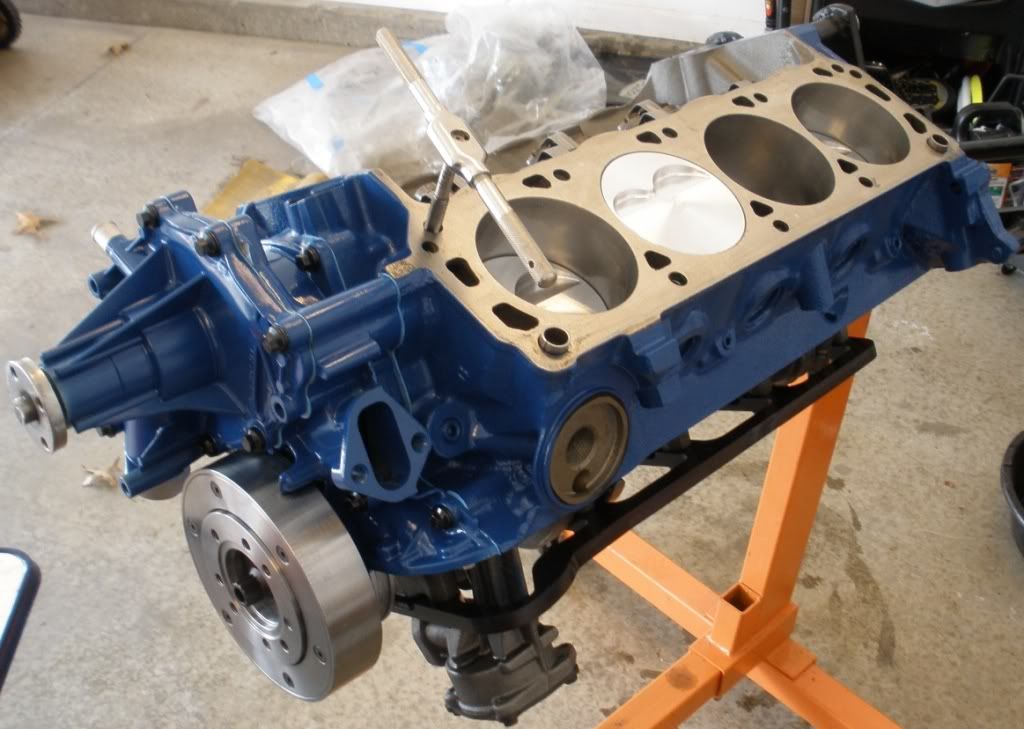
Look at the coolant passages on each end, top and bottom of the block.
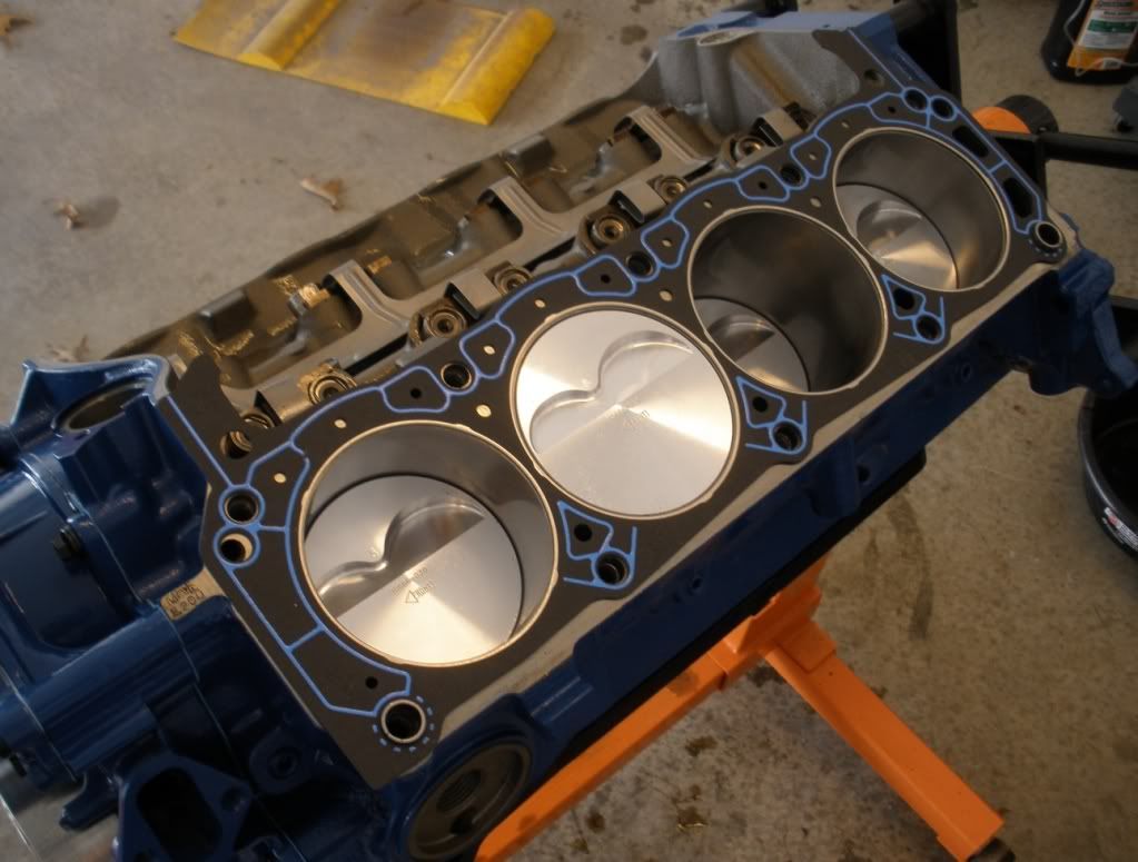
With head gasket on, you can see that the coolant passages at the front of the block are blocked by the gasket except for a small hole. The passages are open at the back of the block. Also notice how the holes in the gasket on the lower side (exhaust side) of the head progressively get bigger as they go to the back of the head. The holes at the top of the head are evenly small. This is to force the coolant through the head at the bottom and back of the head through the head and to the front of the head across the front of the intake manifold and then out through the thermostat to the radiator.
If the holes at the font and top of the block were opened in the head gasket, the engine would overheat due to coolant flow cavitation.
This could apply to the M30/S38 in that they used the head gasket to force a coolant path. Which raises the question....could that coolant path in a FI engine be increased or changed with changes to the head gasket?????????
Last edited by Duke on Sep 04, 2011 8:07 PM, edited 1 time in total.
This makes sense. But then, why wouldn't you simply make the passages sized to manage the proper coolant flow to begin with?  Taken to (not too much of) an extreme, what would happen in a situation where there isn't any head gasket used . . . just an O-ring on the cylinders. ISTR this type of layout on bike engines.
Taken to (not too much of) an extreme, what would happen in a situation where there isn't any head gasket used . . . just an O-ring on the cylinders. ISTR this type of layout on bike engines.Doh!Duke wrote:Engine meltdown. Bike engines air cooled.Ken H. wrote:what would happen in a situation where there isn't any head gasket used . . . just an O-ring on the cylinders. ISTR this type of layout on bike engines.
 Realized that right after I posted. Ken gets 4 simpleton points added to his score.
A good starting point would be to obtain (Brian) a M106, M30, S38 (B35, 36, 38) and M88 (1/3) HG and see what the coolant passage hole delta is between them.Duke wrote:Which raises the question....could that coolant path in a FI engine be increased or changed with changes to the head gasket?????????
-
Murfinator
- Posts: 1482
- Joined: Sep 07, 2007
- Location: ZION - 84032
Sure it's unlikely because most people go the cheap and easy route of just adding more boost until the fuse blows. Besides, haven't you already achieved output in the high 400's with a stock short block, mild B34 porting and a PB cam? My build is going to the next level, building upon your experiences. If you're seeing 460+ it shouldn't take much effort beyond what you've invested to add another 40hp. We shall see.T_C_D wrote:That is highly unlikely.Murfinator wrote: I'm fairly confident my motor will break the 500whp threshold running <14# boost while remaining tractable and reliable.
500rwhp = the same cyl pressure at 14psi as 25psi if the displacement is the same. Air flow is air flow regardless of how you get it into the combustion chamber.Murfinator wrote:This and other factors have led me to avenues other than cranking up >2 bar of boost for producing power.
Believe me, I understand air flow principles fairly well. This revelation led me to sell the cork (B34 and B35 intake manifold) in my motor and opt for ported B36 throttles and a custom plenum. You can boost all you want but if your flow is restricted your output will suffer.
Back to the original topic: speaking of M30 vs. M106 blocks, are there any differences in coolant passages between the two? I didn't think so. I went with the M106 for the piston oilers only.
-
Good & Tight
- Posts: 461
- Joined: Oct 29, 2007
-
Kyle in NO
- Posts: 17638
- Joined: Feb 12, 2006
- Location: Nasty Orleans------> Batten-Rooehjch------>More Souther LA
-
Bill in MN
- Posts: 1718
- Joined: Feb 12, 2006
- Location: The Boonies, Mn
- Contact:

I got away with 1.4 bar for a good year and a half with the old 2.7. Took that motor apart to refresh it, not because the gasket failed. I ran it all out without consideration of any potential cooling system insufficiency. The 2.5 was the one that had the failure for no apparent reason. It could have been a problem with ignition advance that overwhelmed any remaining margin of cooling system capacity.
So is the extent of scientific proof that it is actual design flaws with the cooling system is the fact that the passages look different than a 2J so it must be broken?
Any actual data logs of coolant temp and pressure to support these claims? Such logs would easily confirm these deficiencies.
As an aside I'm still curious to know what this motor is being tuned with and how knock is being detected.
No knock detection? No catalogs of coolant pressure or cylinder head temp data? Then it's all just "theory".
I would not be surprised if the cooling system has some issue that makes it a bit marginal, and then once the cylinder head temps rise on the track you get a bit of mild detonation. This will cause runaway cylinder head temps and headgasket/cooling system issues every time.
Collect some more data and verify the basics are right before you start hogging out cooling passages etc.
Any actual data logs of coolant temp and pressure to support these claims? Such logs would easily confirm these deficiencies.
As an aside I'm still curious to know what this motor is being tuned with and how knock is being detected.
No knock detection? No catalogs of coolant pressure or cylinder head temp data? Then it's all just "theory".
I would not be surprised if the cooling system has some issue that makes it a bit marginal, and then once the cylinder head temps rise on the track you get a bit of mild detonation. This will cause runaway cylinder head temps and headgasket/cooling system issues every time.
Collect some more data and verify the basics are right before you start hogging out cooling passages etc.
Coolant temperature and cylinder head temperature aren't necessarily the same thing. Especially when you have a massive amount of heat flowing through one side of the casting and coolant flowing through another. Datalogs will show a gradual hump for a spike in cylinder head temperature. You would expect to see that under load anyway. BMW moved the CTS to the side of the head on the 24v motors for this reason.
Knock detection is apparently not worth much on these engines. Mechanical noise overwhelms the sensors. Detonation isn't needed to blow a gasket though. Thats just the easy way to do it.
Knock detection is apparently not worth much on these engines. Mechanical noise overwhelms the sensors. Detonation isn't needed to blow a gasket though. Thats just the easy way to do it.
Dan,
I guess I should have been more precise. Yes, logging cooling performance in the head requires that you log data from a sensor installed in the head itself. Data from the sensor in the tstat housing wouldnt mean much. Ideally it is nice to determine what cylinders run the hottest but that can be tough. Intake manifolds like the later m30s have tend to lean out the center cylinders but that's just a guess.
I generally put the sensor on #5 or #6 on inline 6's unless I have a compelling reason not to.
You are right in that some gimmicky electronic device that "detects" knock is iffy on a solid lifter, rocker arm motor. Det cans still work great though. I can distinguish knock just fine with them and from there a electronic system can be calibrated to catch a bad tanks of gas or whatever, but in this case you need to actually listen or record the noise. You might get away with logging and reviewing raw knock sensor data but eh det cans are better.
It's amazing what a few degrees of ignition advance, or 0.3 afr points can have in cylinder head temp. Or even just light detonation because is disturbs the boundary layer in the combustion chamber that insulates the head from combustion.
Sorry to be long winded, either of these topics is a thread of it's own. I come from tuning open deck aluminum block volvo motors and have spent some time working on these issues (because if you get it wrong with one of those motors, you split a liner) so was interested to see if anyone is getting very deep into really understanding the ins and outs. I like conclusions based on real data and the dubious assumptions that some times quickly become "fact" on the Internet are unfortunate. seemed like that might have been happenIng in this thread so I thought I'd mention that there are things one could check. My motors will always have a temp sensor in a meaningful spot and will be dyno tuned and subsequently tested using det cans. and if I lose a head gasket, there is a very good chance I will know exactly what conditions caused it.
I guess I should have been more precise. Yes, logging cooling performance in the head requires that you log data from a sensor installed in the head itself. Data from the sensor in the tstat housing wouldnt mean much. Ideally it is nice to determine what cylinders run the hottest but that can be tough. Intake manifolds like the later m30s have tend to lean out the center cylinders but that's just a guess.
I generally put the sensor on #5 or #6 on inline 6's unless I have a compelling reason not to.
You are right in that some gimmicky electronic device that "detects" knock is iffy on a solid lifter, rocker arm motor. Det cans still work great though. I can distinguish knock just fine with them and from there a electronic system can be calibrated to catch a bad tanks of gas or whatever, but in this case you need to actually listen or record the noise. You might get away with logging and reviewing raw knock sensor data but eh det cans are better.
It's amazing what a few degrees of ignition advance, or 0.3 afr points can have in cylinder head temp. Or even just light detonation because is disturbs the boundary layer in the combustion chamber that insulates the head from combustion.
Sorry to be long winded, either of these topics is a thread of it's own. I come from tuning open deck aluminum block volvo motors and have spent some time working on these issues (because if you get it wrong with one of those motors, you split a liner) so was interested to see if anyone is getting very deep into really understanding the ins and outs. I like conclusions based on real data and the dubious assumptions that some times quickly become "fact" on the Internet are unfortunate.
seemed like that might have been happenIng in this thread so I thought I'd mention that there are things one could check. My motors will always have a temp sensor in a meaningful spot and will be dyno tuned and subsequently tested using det cans. and if I lose a head gasket, there is a very good chance I will know exactly what conditions caused it.-
FirstFives Dictator
- Posts: 849
- Joined: Feb 12, 2006
- Location: Virginia Beach, VA
- Contact:
-
Rich Euro M5
- Posts: 6098
- Joined: Mar 10, 2006
- Location: Klein, Texas
Everyone is over thinking the purpose of the HG holes. They are to limit flow which allows time for the coolant to pick up heat from the head. The coolant has to stay in contact for a given amount of time to pick up the heat, when flow is too high you loose efficiency. It's also critical to run the correct glycol / water mixture for maximum cooling efficiency. Straight H2O has the best heat transfer characteristics but a lower boiling point than a glycol / water mix. The glycol reduces the heat transfer, but the temps can be higher before the coolant boils, therefore it's a compromise. Coolant system pressure also impacts the boiling point. This is one of the differences between the S38, M106, and M30 cooling systems. The S38 and M106 cooling system utilizes a 1.4 Bar pressure while the M30 has a 1.0 Bar pressure. One could conceivably run less glycol, just enough for corrosion protection but better heat transfer characteristics. The downside would be a lower boiling point, but that could be mitigated by running a higher system pressure to increase the boiling point of the coolant.Ken H. wrote:I can understand the logic of having coolant coming into the head initially on the exhaust side, but will someone please explain why the coolant openings in the HG are significantly smaller than the passages in the block ?Bill in MN wrote:Ever notice how small the coolant holes are on the intake side of a HG? They're a fraction of the size of the passages in the block and head.
Other parts of the engine cooling should be considered as well, namely oil capacity and cooling. The Euro e28 535i had an oil cooler, while US/NA versions do not. There's a reason, additional cooling needs of extended high speed driving on the Autobahn. Increasing oil capacity will help, either through use of a larger sump or ditching the wet sump system and incorporating a dry sump system as is done with some racing engines.
Just my $.02.
Rich
Last edited by Rich Euro M5 on Sep 05, 2011 12:16 PM, edited 1 time in total.
-
Rich Euro M5
- Posts: 6098
- Joined: Mar 10, 2006
- Location: Klein, Texas
A/F ratios have a huge impact on cylinder pressure. Highest cylinder pressure will occur with AFRs which cause EGTs at 75 F to 100 F rich of peak. Most HP also happens here, probably close to detonation starting , and highest cylinder pressure, ie; head bolt stretch and HG failure. However peak HP doesn't denote peak efficiency. When EGTs get inside of 50 degress rich of peak, EGT, cylinder pressures will drop rapidly, and HP decreases slightly. Continue leaning until past peak EGT and HP will not change much from 50 degrees F rich to 50 degrees F lean of peak, However cylinder head temperatures will decrease and engine longevity will be improved. Running lean of peak is done routinely in large displacement, flat 6 aircraft engines.Kenny wrote:It's amazing what a few degrees of ignition advance, or 0.3 afr points can have in cylinder head temp. Or even just light detonation because is disturbs the boundary layer in the combustion chamber that insulates the head from combustion.
However nobody here (except Ken H.) has instrumented their turbo cars to monitor the impact A/F ratio and density altitude has on EGT and TIT.
Just my $.02.
Rich
Last edited by Rich Euro M5 on Sep 05, 2011 1:07 PM, edited 1 time in total.
-
paul burke
- Posts: 844
- Joined: Sep 08, 2008
- Contact:
Good & Tight wrote:Duke wrote:I've said it before....saying it again. The M30 is not a good design for Forced Induction.
This is one of the reasons why boost over 13 psi on a M30 won't last.Duke were you high when you wrote this?
I'm hallucinating just trying to make sense of all the crap I'm reading here!!
I think most of you busted into the beer to early

Most common cause of head gasket failures? AFRs south of 11.85!
Paul
OK, I won't argue the point or the number, but a few questions, Paul:paul burke wrote:Most common cause of head gasket failures? AFRs south of 11.85!
1. Does the 11.85 # apply to NA or boosted motors or both, or is it related in some way to BMEP? Does a higher BMEP point toward a lower A/F number?
2. What kind of changes, richer or leaner, need to be taken into consideration at altitude? This would apply more to NA motors rather than FI, I would think.
3. In setting up the A/F tables on a standalone engine management system, typically one richens A/F as boost pressure rises. For example, I have used 11.5 A/F where boost is in the 12-15 psi regime. This was done out of an abundance of caution to avoid detonation under boost. If one were to move the A/F number up to 11.85 from 11.5 this is about a 3% leaner value. Does this imply that the values in the A/F table matrix all need to be leaned out by 3%, or is there some algorithm that should be used as one moves from vacuum to progressively higher levels of positive pressure?