External links now open in a new browser tab - turn this off in your UCP - Read more here.

Blunttech e12 LSx / t56 swap

E28 technical advice asked and given! Troubleshooting, modifications and more.
jakeb
Posts: 552
Joined: May 07, 2011 11:30 PM
Location: Bay City, MI
Contact:

Post by jakeb »

Small update...
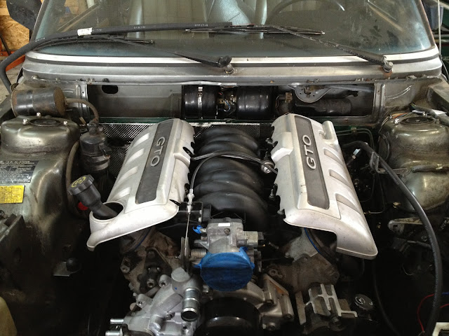
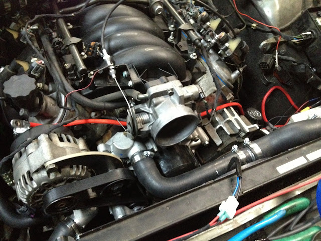
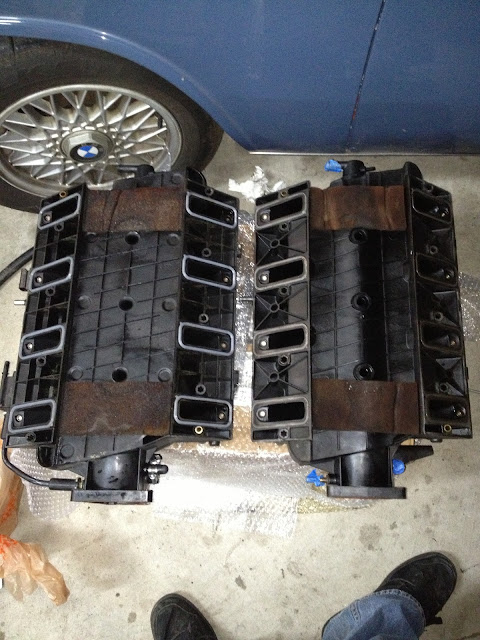
Here is the difference between an LS1 intake and LS6 intake. The LS6 is on the left. They look the same on the top but on bottom the LS6 is flat...it is bigger on the inside and good for 15-20hp on it's own.
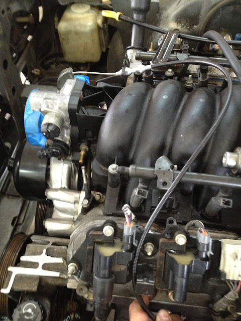
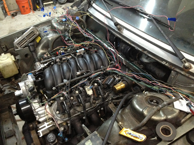
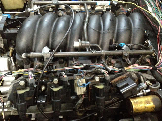
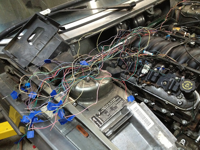
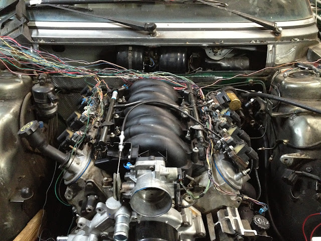
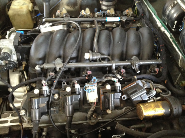
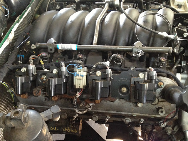
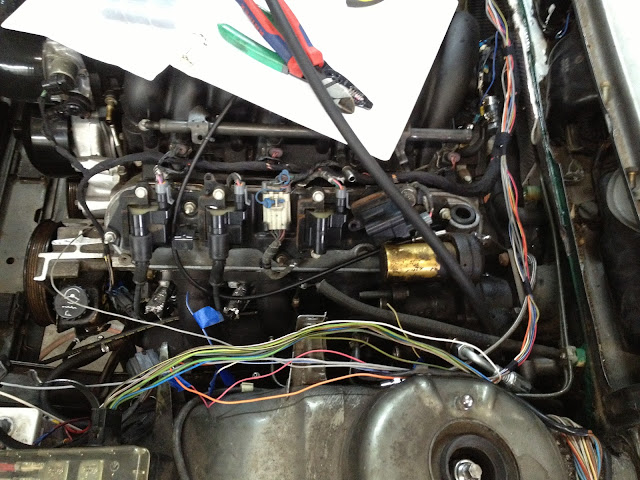
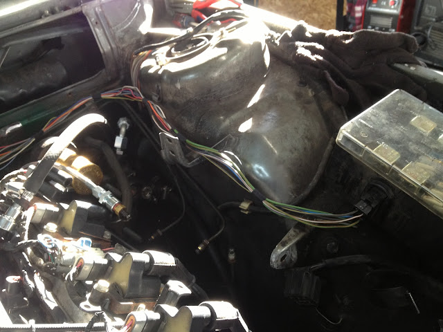
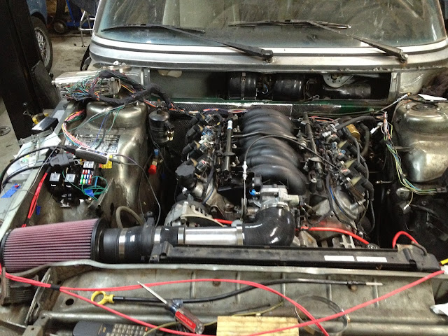
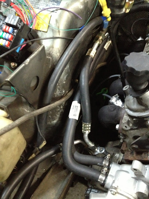
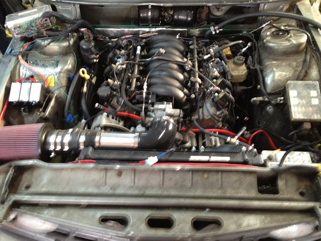
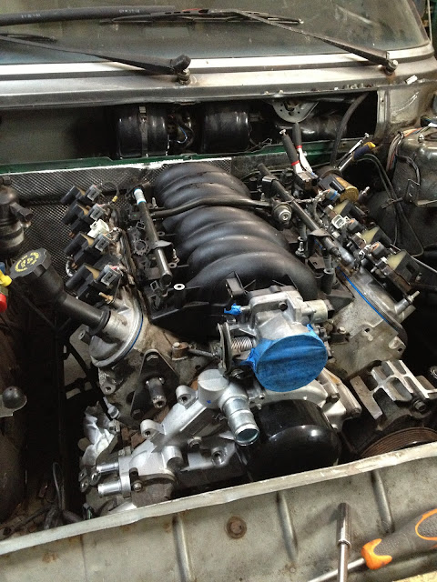
Image

On the engine
Image

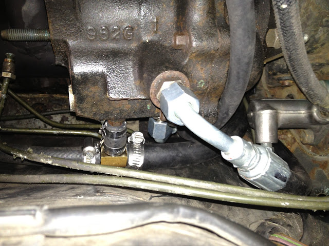
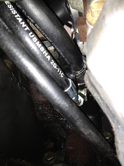
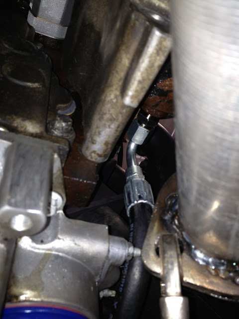
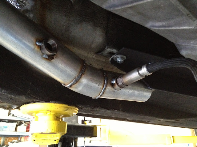
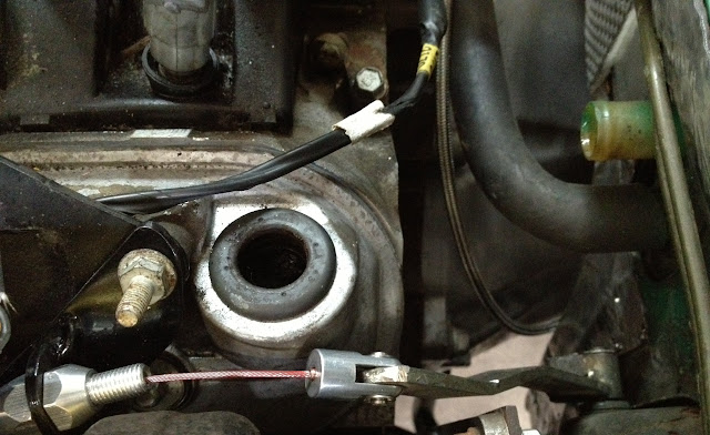
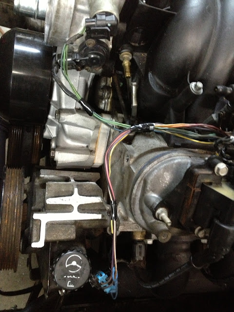
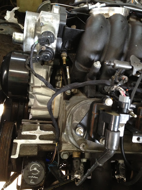
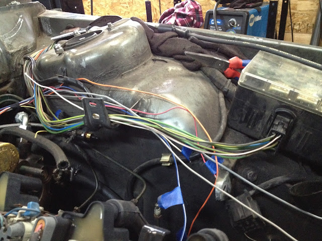
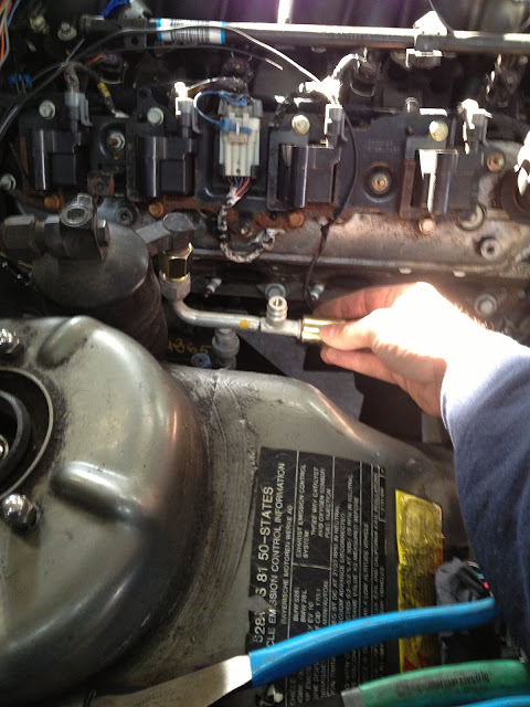
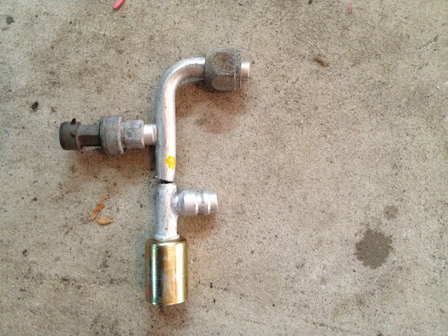
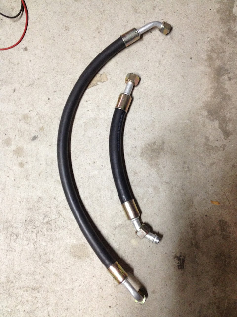
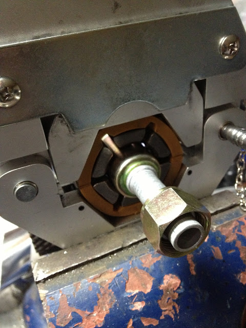
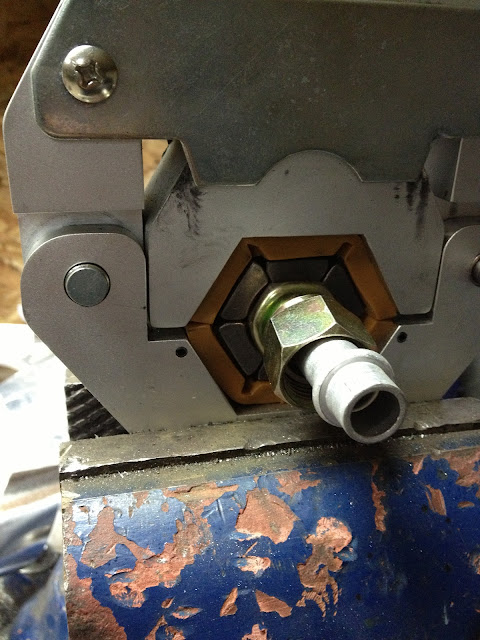
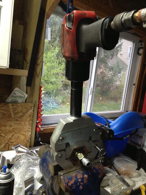
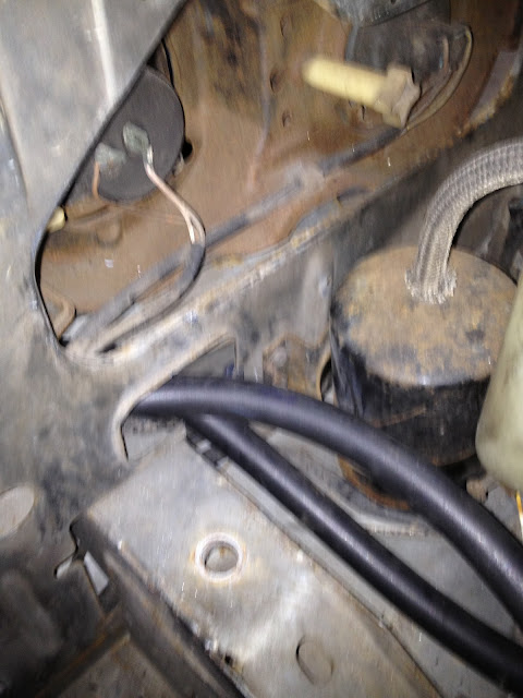
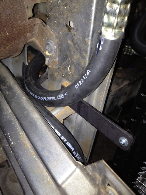
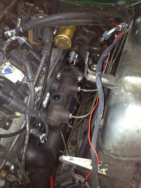
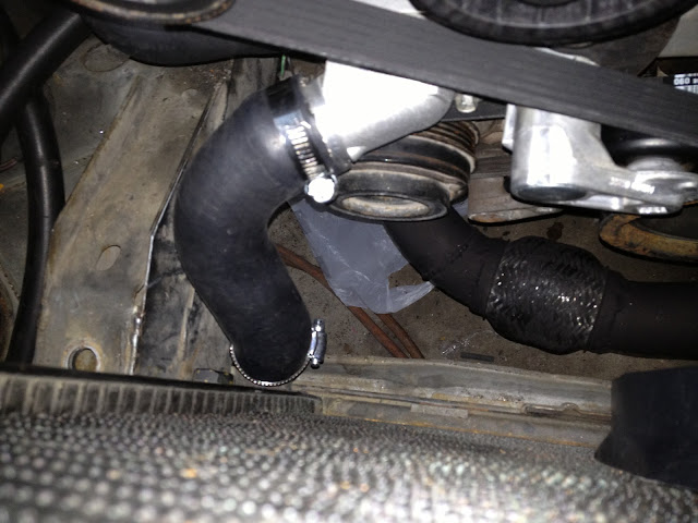
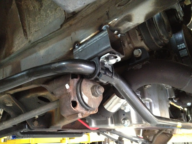
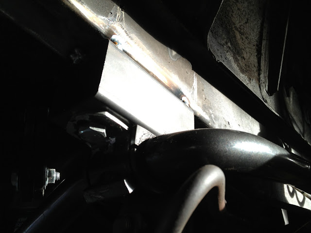
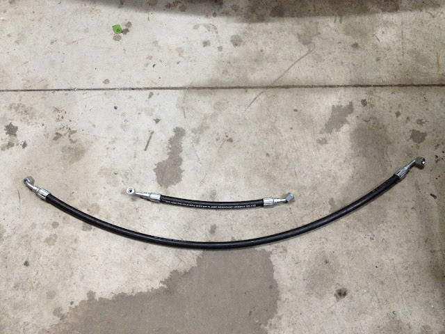
Power steering/hydroboost lines are made
Image

Other things done or at least figured out but no pictures of...
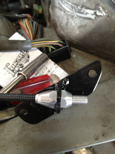
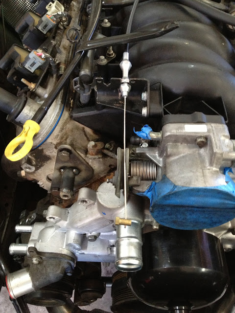
throttle cable
power steering/hydroboost return lines (they have to T into each other)
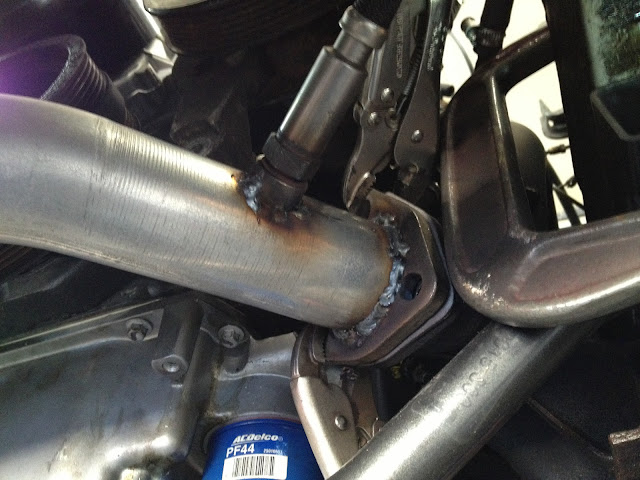
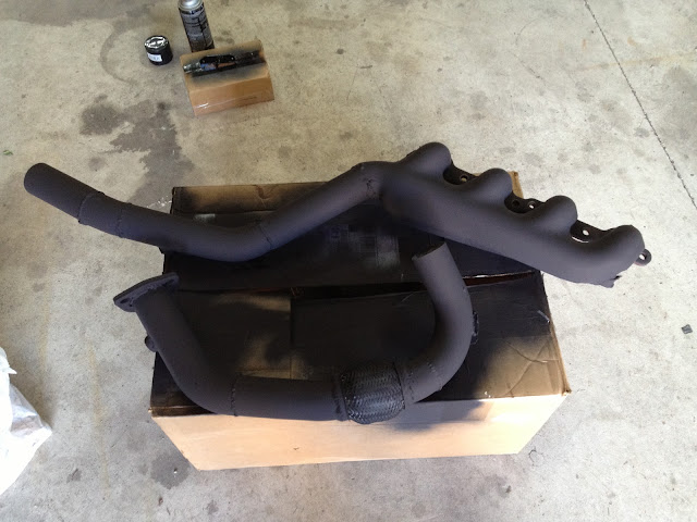
Drivers side exhaust manifold bolted on for the last time (I love putting things on for the last time)
jakeb
Posts: 552
Joined: May 07, 2011 11:30 PM
Location: Bay City, MI
Contact:

Post by jakeb »

Saturday lunchtime update.

Hard to really get pictures of this..but it all the high pressure lines from the power steering pump to the steering rack and the hydroboost. The T you see here is the return from the steering box and then from the hydroboost.

Image

Lines coming off steering box
Image

Connection at the pump
Image

Oxygen sensor bungs tacked in...just need to fully weld
Drivers side..
Image

Passenger side...added an extra here in case I want to log some data with my wideband and HP tuners.
Image

Shifter coming up through...using the stock camaro stuff for now.

Image
jakeb
Posts: 552
Joined: May 07, 2011 11:30 PM
Location: Bay City, MI
Contact:

Post by jakeb »

Plugging away...

O2 bungs fully welded and the remainder of the exhaust is painted with high temp paint.

Image

Throttle cable bracket
Image

Where it connects to the e12 lever. The throttle lever on the e12 normally is much lower and pointing down. It actually pushes when you push down on the pedal and uses a bunch of linkages up to the throttle body. For it to work with a cable it needed to pull... I was able to rotate it so the arm was pointing up and make it into a puller.

Image

Then it loops around the intake.
Image

Where it hooks to the throttle body
Image

The coil for cylinder #7 had to be moved a little bit
Image

GTO engine covers...they will need a little trimming on the drivers side to fit but they should work nicely
Image
unt0uchable
Posts: 2265
Joined: Jul 21, 2011 8:05 PM
Location: Rochester Hills, Michigan
Contact:

Post by unt0uchable »

Looking slick as usual. Can't wait to see a video of this beast tearing through some gears. Keep it up Jake!
jakeb
Posts: 552
Joined: May 07, 2011 11:30 PM
Location: Bay City, MI
Contact:

Post by jakeb »

thanks man!

Started on putting the engine harness back together.

Lay it back on the engine and start plugging wires in.

Image

Pull them together and tape every time a wire goes in or out of the loom.
Image

Just keep going along
Image

That's a lot of wires....
Image

Looking better....
Image
jakeb
Posts: 552
Joined: May 07, 2011 11:30 PM
Location: Bay City, MI
Contact:

Post by jakeb »

Took today to try to wrap it up....wiring is taking longer than I expected. But progress none the less.

I laid the harness back out on the engine....now off the engine and repinned to the connectors. Looking like the PCM will reach into the glovebox.

Image

Rewrapping the harness
Image

Laying it back out on the engine
Image

Image

Image

Image

Still more to clean up...wires can be tied into the e12 harness now..
Image

The extra fuse/relay box.

Image

Intake is coming together
Image

Now I wasn't expecting that filter was going to be that big....

Both of these filters have a 3.5" inlet.... The one on the right really isn't that small either.
Image

The filter I ordered is just about the same size as my head.
Image
jakeb
Posts: 552
Joined: May 07, 2011 11:30 PM
Location: Bay City, MI
Contact:

Post by jakeb »

More wiring....engine side is done and all wrapped up for the most part. Still need to connect the grounds. Next up I can tie the LSx harness into the BMW harness. The e12 has some weird wiring so I am trying to track down where the fuel pump feeds from.

Some pictures....

Made the hole bigger going into the car
Image

PCM connectors reach without extending wires!! very good
You can also see the wires separated coming from the extra fuse box.
Image

You can't really see but where the wires turn towards the inside of the car I make some little marks with a marker so I can keep things lined up.

Image

Then just like a cooking show...20 minutes in the oven and we are done
Image

OBDII Port and other wires that will go into the cabin, CEL, VSS signal for speedo, power/ground for speedo, and one extra power line. (wideband for tuning if needed)
Image

Wires over at the drivers side where they will tie into the fuse box. coolant temp, oil psi, tach, fuel pump, 12v switched, start signal
Image

Just another angle showing the routing.
Image
Jelmer538i
Posts: 1222
Joined: Feb 12, 2006 12:00 PM
Location: Netherlands
Contact:

Post by Jelmer538i »

Looks like its almost ready to run!
1st 5er
Posts: 21886
Joined: Jun 13, 2008 12:15 AM
Location: Cypress
Contact:

Post by 1st 5er »

jakeb wrote: That's a lot of wires....
Image
I think I'd rather have a tooth pulled.
jakeb
Posts: 552
Joined: May 07, 2011 11:30 PM
Location: Bay City, MI
Contact:

Post by jakeb »

Yes it is getting really close to being able to fire it up
jamesohoh7
Posts: 203
Joined: Oct 05, 2011 8:46 AM
Location: Katy, Tx

Post by jamesohoh7 »

1st 5er wrote:
jakeb wrote: That's a lot of wires....
Image
I think I'd rather have a tooth pulled.
pulled then surgically re-implanted upside down ... would STILL be less painful! :rofl:
jakeb
Posts: 552
Joined: May 07, 2011 11:30 PM
Location: Bay City, MI
Contact:

Post by jakeb »

haha, why do people hate wiring so much? It's really NOT that scary. Once you spend hours upon hours of reading and looking at schematics. :shock:
Brad D.
Beamter
Beamter
Posts: 10735
Joined: Feb 12, 2006 12:00 PM
Location: San Antonio, TX
Contact:

Post by Brad D. »

jakeb wrote:haha, why do people hate wiring so much? It's really NOT that scary. Once you spend hours upon hours of reading and looking at schematics. :shock:
I'm the same way. I don't really get the general fear of wiring that so many have. Dare I say I actually enjoy wiring. :shock:
jakeb
Posts: 552
Joined: May 07, 2011 11:30 PM
Location: Bay City, MI
Contact:

Post by jakeb »

Little bit by little bit....

Wires going to the crank sensor, starter solenoid, and gauge temp sensor. Wraped in heat tape as they are all pretty close to the exhaust. That is how GM does it as well so...
Image

New harness tied into the e12 fuse box. These wires will get wrapped.
Image

AC pressure fitting that needs to be brazed together
Image

Image

A couple other things done but no pictures...or really pictures required.
Negative cable to block/battery
fuel line connected
tn535i
Posts: 5590
Joined: Jul 14, 2006 1:30 PM
Location: Middle Tennessee

Post by tn535i »

jakeb wrote: sound deadening on the firewall
Image

covered with some heat reflection stuff
Image
Been watching this and have a question about the sound deadening and heat reflection material. What have you used here. Looks good and might consider on our e30 project. That rubbery piece of stuff from our cars wasn't worth trying to re-install.
jakeb
Posts: 552
Joined: May 07, 2011 11:30 PM
Location: Bay City, MI
Contact:

Post by jakeb »

It is two different products. First a stick on sound deadening type material. Dynamat style...lots of different brands out there.

Then the heat reflection stuff I use is DEI Floor and tunnel shield. I get it from summit racing.
jamesohoh7
Posts: 203
Joined: Oct 05, 2011 8:46 AM
Location: Katy, Tx

Post by jamesohoh7 »

Brad D. wrote:
jakeb wrote:haha, why do people hate wiring so much? It's really NOT that scary. Once you spend hours upon hours of reading and looking at schematics. :shock:
I'm the same way. I don't really get the general fear of wiring that so many have. Dare I say I actually enjoy wiring. :shock:
Once you let the smoke out of the wires, it's really hard to get it back in is all... :D
jakeb
Posts: 552
Joined: May 07, 2011 11:30 PM
Location: Bay City, MI
Contact:

Post by jakeb »

Plugged the PCM in about 30 minutes ago and powered it all up. PCM primed the fuel pump and is working. Did a read entire with HP tuners so I can pull out VATS and other unneeded things. VATS is like EWS in the BMW world.

I did have one issue with how the unloader relay works...when I turned the key to on (not crank) the engine started cranking. I used a start relay because that is how GM does it and the fuse/relay panel I got came wired that way. I will just have to run a wire direct to the starter solenoid the way BMW wants it. Easy fix....

e12 with an OBDII Port connected to a laptop....... :)
Image
tn535i
Posts: 5590
Joined: Jul 14, 2006 1:30 PM
Location: Middle Tennessee

Post by tn535i »

Since the key 'run' position sends power to the unloader relay coil it gets immediately energized but only de-energized when you apply power to the starter solenoid since the unloader coil is actually grounded through the starter coil. So the unloader 'unloads' when you apply power to the starter coil. If you put the GM start relay in that position it probably gets enough power from the current passing through the unloader relay coil to energize the GM relay. You probably already figured that out.

You will have to split out the BMW unloader relay and take it to the coil energize output of the GM relay to get the unloader to work as intended I think. Then apply the start signal to the GM start relay. A separate wire from the BMW start may still be tied into the unloader in the harness. If you just run a separate wire to the GM relay you would have the same problem. If you lift the start altogether from a grounded termination then the unloader relay will never energize. Or will you just eliminate the GM relay?

Hope I said that right. You probably know this anyway.

Anxious to see this going and following your progress.
jakeb
Posts: 552
Joined: May 07, 2011 11:30 PM
Location: Bay City, MI
Contact:

Post by jakeb »

I plan to just run the start wire direct to the starter like BMW wants it. Then the unloader will get ground when not in cranking mode. I checked the start pin on my e28 with the c101 unplugged and I was also seeing 12v so it is the same as the e12.
jakeb
Posts: 552
Joined: May 07, 2011 11:30 PM
Location: Bay City, MI
Contact:

Post by jakeb »

Intake setup is made...the filter might need to change to something a little smaller...not sure if the hood will close. But it will work for now.

Image

Image
jakeb
Posts: 552
Joined: May 07, 2011 11:30 PM
Location: Bay City, MI
Contact:

Post by jakeb »

It's running!!

I can never remember how to flip the iphone to get the right orientation for youtube....

Either way here are a couple videos. I will get some better ones eventually.
The little light in the engine bay is a oil pressure light. You can hear it quiet down once the light goes off.

This is the first start
http://www.youtube.com/watch?v=39tCSraGwUE&feature=plcp

A little blip...you can hear a slightly choppy idle from the cam.
http://www.youtube.com/watch?v=tv6A3z0JotU&feature=plcp
1st 5er
Posts: 21886
Joined: Jun 13, 2008 12:15 AM
Location: Cypress
Contact:

Post by 1st 5er »

That makes it all worth it.

Congrats.
Mark 88/M5 Houston
Posts: 8548
Joined: Feb 12, 2006 12:00 PM
Location: Far North Houston

Post by Mark 88/M5 Houston »

Great sounding E12 there sir! :alright:
jakeb
Posts: 552
Joined: May 07, 2011 11:30 PM
Location: Bay City, MI
Contact:

Post by jakeb »

thanks guys, glad it is running! After a little research it looks like the pushrods are a little short. So I have a set of 7.450 on order. The ones in it now are 7.400. That should add a bit more preload on the lifters and quiet down the valve train some.

Worked on the AC lines today.
These are the crimped low side to compressor (short line) and high side from compressor to condenser.
Image

In the tool and pre crimp
Image

post crimp
Image

Entire crimping tool/setup
Image

Heater hoses also done...AC lines feeding up to the drier (not connected yet) and the low side to the evap.
Image


Bad picture...but where it goes up front..
Image

Other side before it goes to the condenser.
Image

Hooking to the condenser
Image
jakeb
Posts: 552
Joined: May 07, 2011 11:30 PM
Location: Bay City, MI
Contact:

Post by jakeb »

Master cylinder is back on....getting those lines all hooked up was a BITCH. Mostly the ones on the bottom. Hard to push up and turn at the same time.
Either way it is hooked up......#5 coil will have to be relocated a little to clear the reservoir.

Image

Upper radiator hose and efan. I looked for a single hose but couldn't find anything to do what I wanted/needed. So two hoses with a coupler will work. efan is a 16" puller...high and low speed controlled by the GM PCM.

Image

As luck would have it the lower hose worked out being the left over piece/bend from the upper hose hooked to the radiator.

Image

alternator/belt/etc are all on
Image
jakeb
Posts: 552
Joined: May 07, 2011 11:30 PM
Location: Bay City, MI
Contact:

Post by jakeb »

New sway bar mounts tacked on. Once I am happy with them it will get fully welded.

Image

Image

I was able to get the end link connected...it is at a slight angle. When I go to have it aligned I will look it over a bit better as the weight will be fully on the wheels and I can see how everything is sitting. End links are not fully tightened as well.

Image

Image

blurry pic but it is coming along....
Image
jakeb
Posts: 552
Joined: May 07, 2011 11:30 PM
Location: Bay City, MI
Contact:

Post by jakeb »

So the e12 has a mechanical speedo.... The t56 does not have a speedo drive but it does have a VSS sensor and the PCM has a VSS output.

So....electric speedo conversion.

Electric VDO Speedo glued to the old metal face.
Image

New face on the left...to be glued to the gauge on the right. The stock e12 needle will get pushed on.

Image

Glued on...the bottom little white bit with get trimmed off. I just needed something to hold onto while it was being glued
Image

Will reassemble into the gauge cluster later today.
Jelmer538i
Posts: 1222
Joined: Feb 12, 2006 12:00 PM
Location: Netherlands
Contact:

Post by Jelmer538i »

Nice speedo! I like it when people think about things like this!
jakeb
Posts: 552
Joined: May 07, 2011 11:30 PM
Location: Bay City, MI
Contact:

Post by jakeb »

Speedo is done...

I was going to mount the odometer/trip button in the under column panel but then I noticed how the odometer reset worked for the mechanical speedo.

Image

Add a button..
Image

Image

All put together
Image

Image

Image

Image

In the car
Image

How it all works..... I think it came out pretty stock looking.
http://www.youtube.com/watch?v=g-d8tOvXeekl
Post Reply