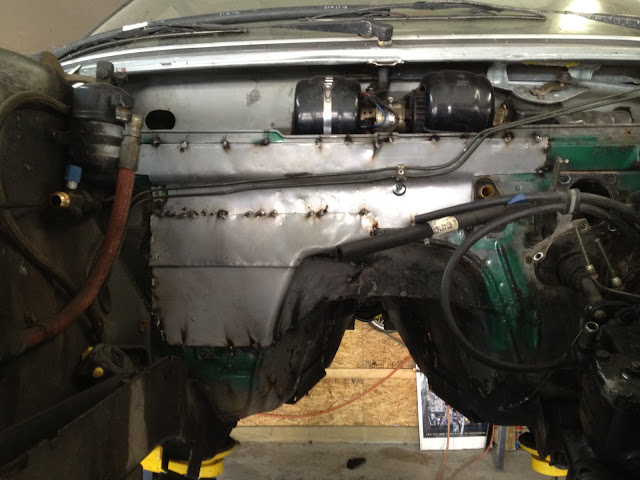
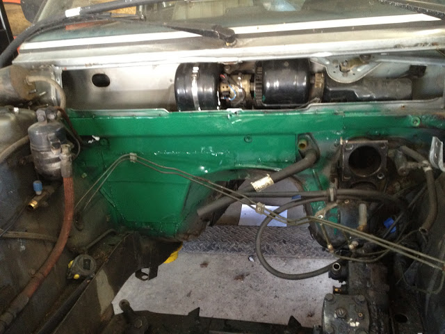
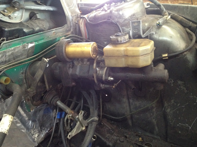
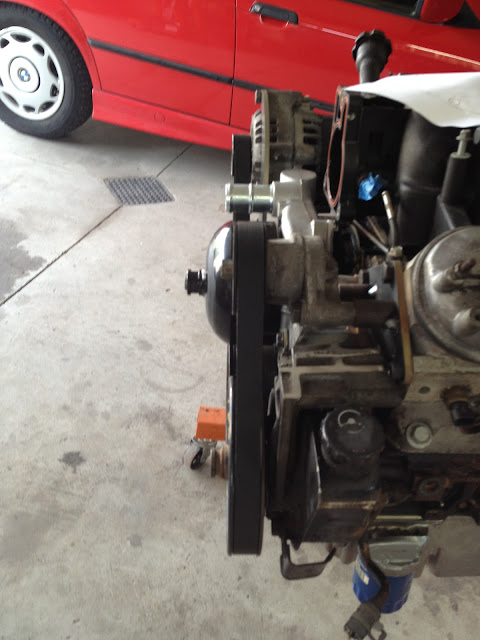
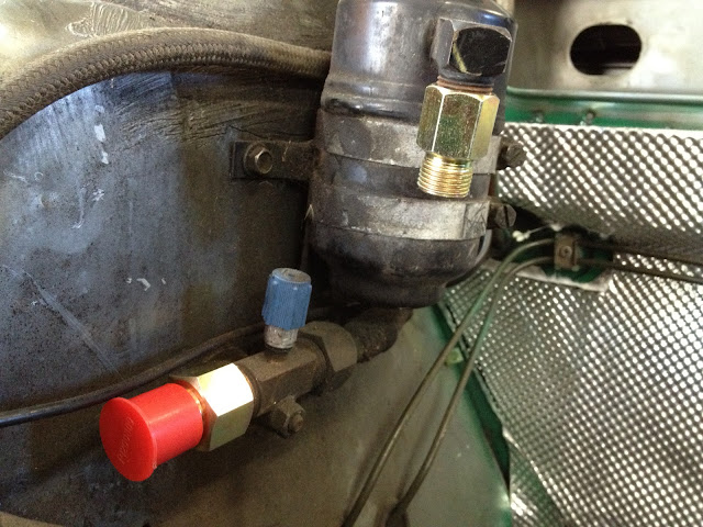
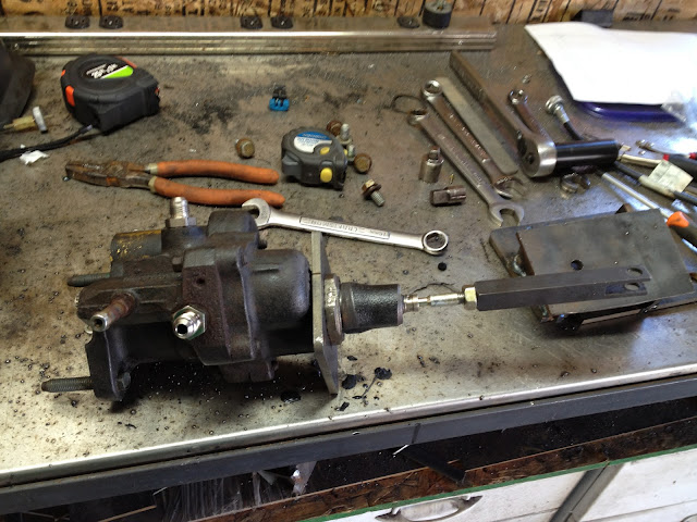
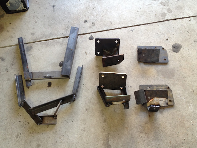
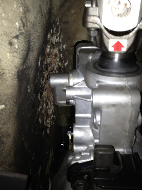
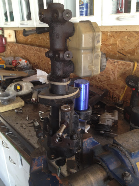
From top to bottom....BMW master cylinder, plate to bolt to MC, adapter pin, short piece of pipe, plate to bolt to hydro boost, hydro booster, plate to bolt to firewall.
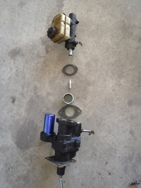
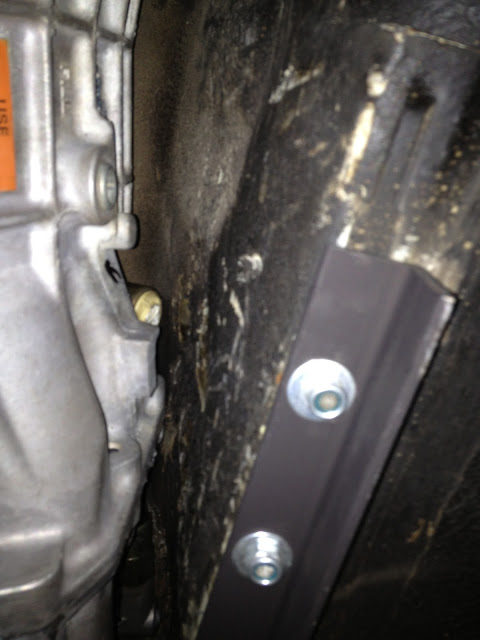
Plate to bolt to firewall...this one is centered but the one currently on the hydro boost is offset some.

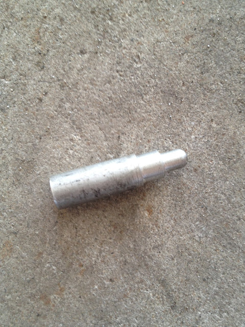
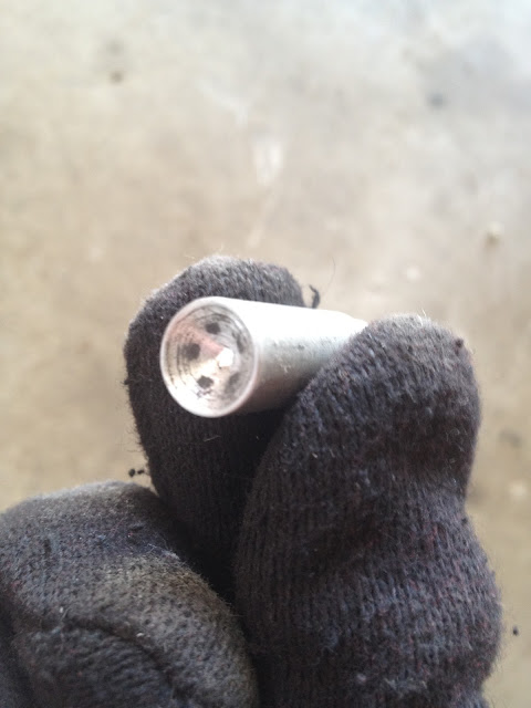
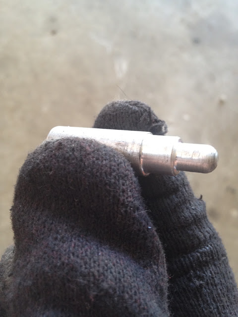
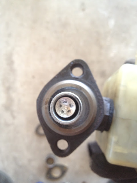
Pin to go inside the MC plunger....nice to have friends with CNC lathes.
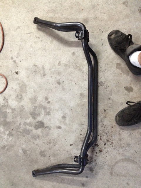
All stacked up...plates will be welded to the pipe.
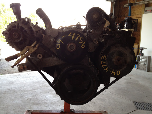
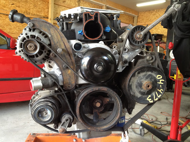
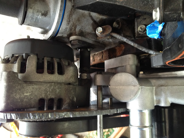
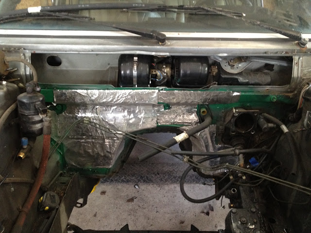
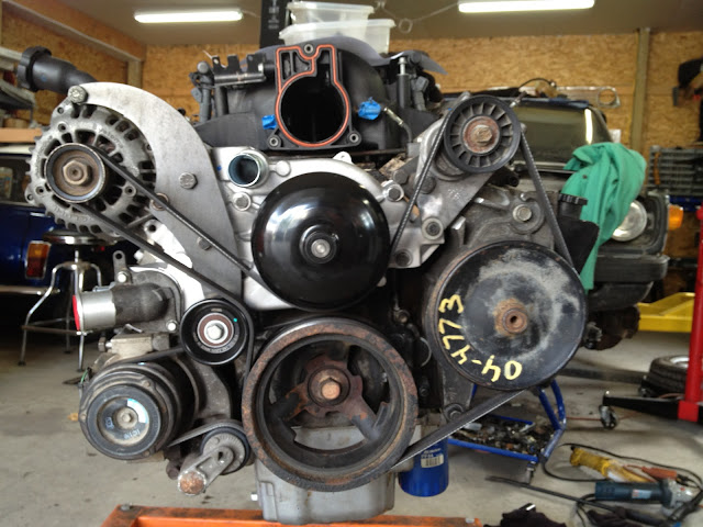
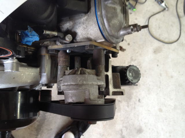
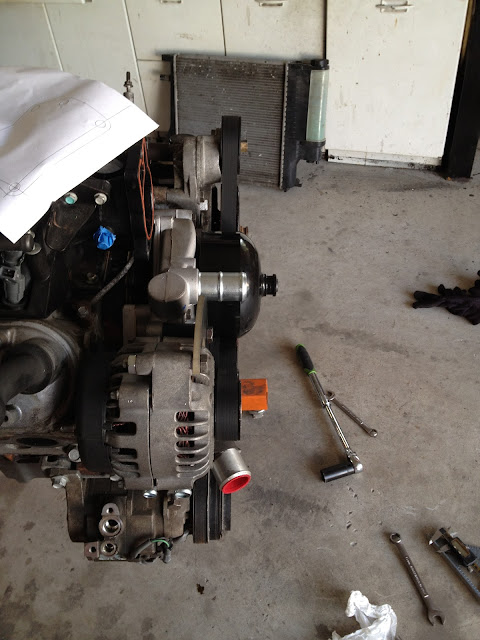
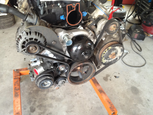
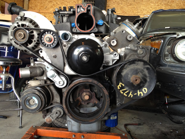
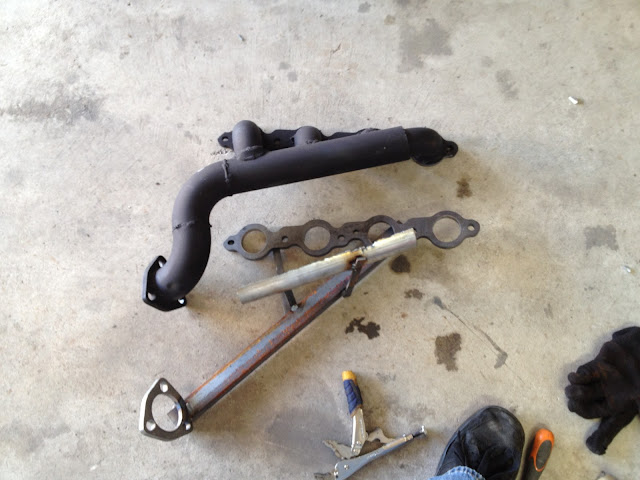
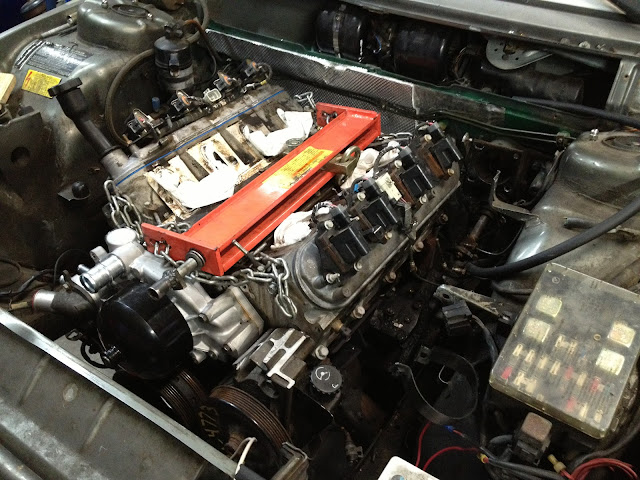
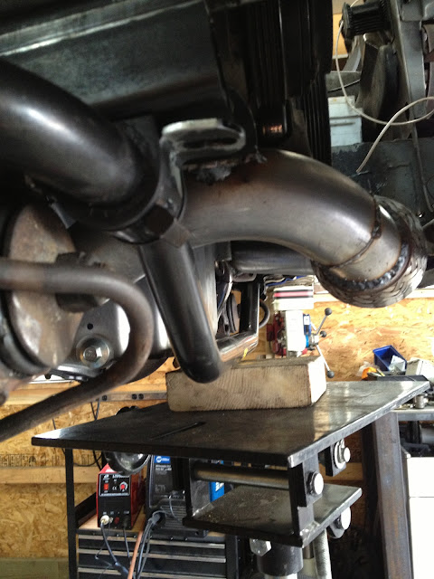
I am using as many of the truck accessories and have to move some things around. There will be a bracket that bolts off the head and two spots on the water pump to hold the alternator. Also need to make a new bracket for the tensioner.
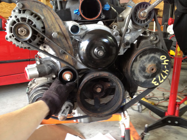
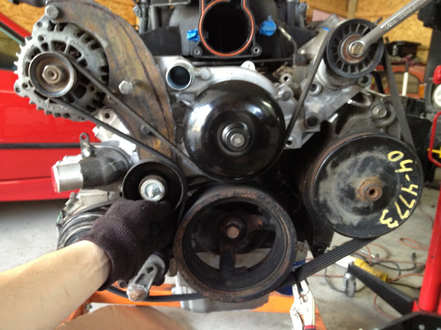
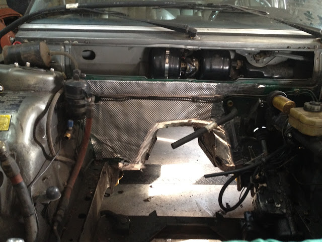
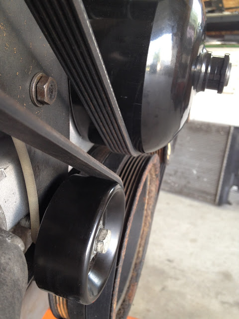
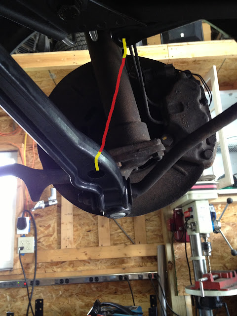
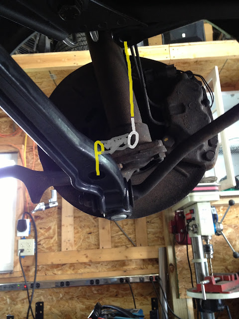
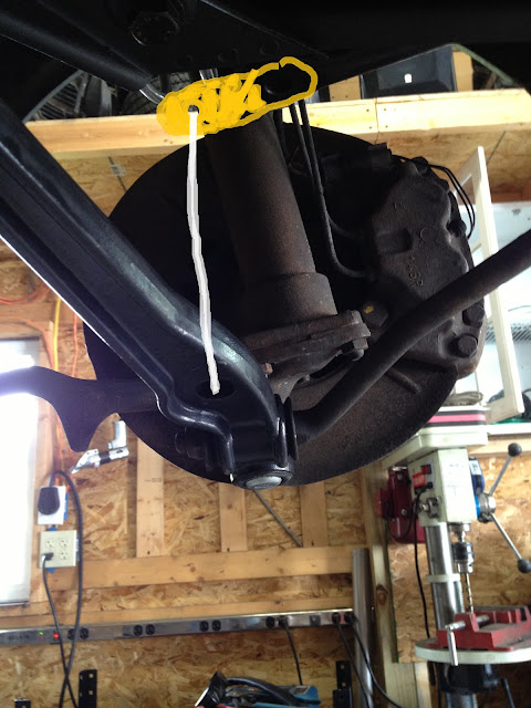
Debating adding another idler to allow a bit more belt wrap on the crank pulley. Leaning towards using the idler rather than not.
with...
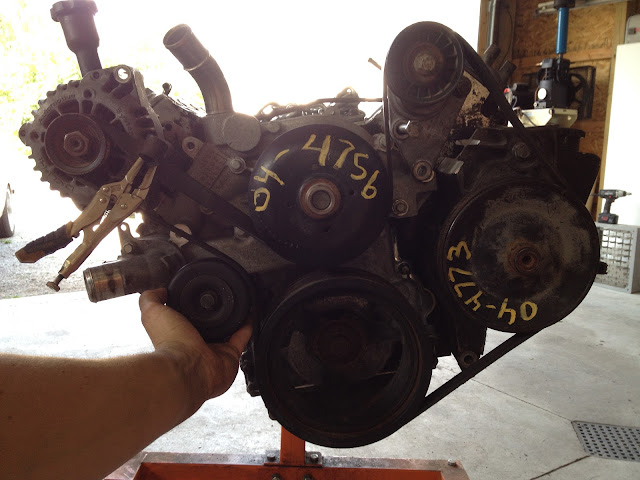
without