Page 15 of 15

Re: 535is Homebrew Turbo (ex 633 Callaway) - 2024 Update

Posted: Aug 28, 2025 2:29 PM
by harrypalmer
I guess I am one of the “few” but I follow you and truly admire your dedication and effort. Sorry about your accident. Which lead me to think ( and I apologize before hand if I am being too forward) that you are a very technical mind, too much (imo) I get lost sometimes.

And with this old-new to you shell, it’s a perfect opportunity to make things right and more presentable  to visually enjoy 😉. Consider balancing both technical skills and art direction. I would say, don’t reinvent the wheel and place that oil cooler where it belongs, for example.
Again, please pardon my criticism. Good luck with your project. 

Re: 535is Homebrew Turbo (ex 633 Callaway) - 2024 Update

Posted: Aug 31, 2025 2:54 PM
by Nebraska_e28
Good to hear you're still alive & kicking!  It's been a while. 
A Couple years ago an old lady that shouldn't have been driving partially crumpled the front of my turbo. I'm still on the fence about repairing let alone finding the energy. 
This is a prime opportunity for you to rebuild yours reimagined bigger and better in the new chassis!  Keep pushing.  

Man it's been a while since Pagosa. That was an amazing drive for us to get there! 

Re: 535is Homebrew Turbo (ex 633 Callaway) - 2024 Update

Posted: Sep 02, 2025 4:12 PM
by tschultz
Thanks for the thought LJ, and good point!

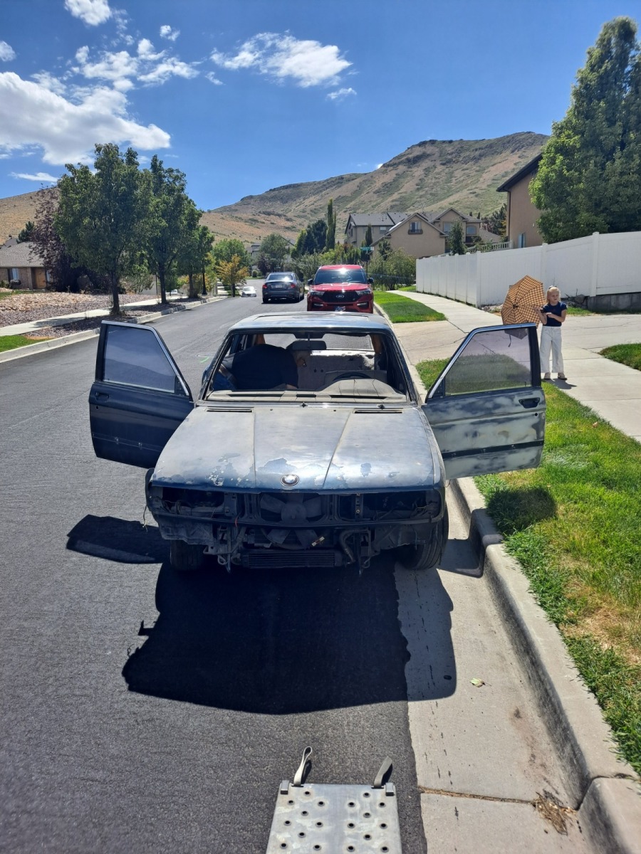
I wanted to paint the car anyway, so in some senses this gets me closer to doing it (but obviously further from just enjoying the car and all of the setup that I had put time into). But it will be a bit of an expensive mistake to repair. Prices of items have gone up... 

I ordered a radiator and some parts and am contemplating what my engine plan will be exactly. I am tempted to put the car back together and track down  mechanical bits after repainting the body. 

I suspect the timing chain tensioner/guide maybe is broken and needs to be disassembled and inspected to confirm. But it may be just as easy to build up my spare B35 block, and trans and drop it in as disassembling this engine, replacing the guide or other parts only to find that it still has some other issues internally.

I started straightening out a few small dents  in the body and on the nose panel as it had been pushed in an inch or so. I started sanding down the hood to see about getting it looking good. I just and ordered a few other parts and hardware to install a differential, axle shafts as the first step to putting things back together.

I also spent a little time removing window tint. Lots of things that need attention mean there is a long list on this project! I will need to replace the intercooler and reconsider the charge piping and if I want to try to keep AC or not. 

Re: 535is Homebrew Turbo (ex 633 Callaway) - 2024 Update

Posted: Nov 14, 2025 11:02 PM
by tschultz
So with the new chassis at home, I started working on sorting it and getting it ready for the DIY paint. I figured I could make it look good enough!

There were a lot of things I needed to do, like pulling out a kink in the nose, grinding out rust in the rear trunk seal area, removing the old tint from the windows, aligning the hood, hammering out the front tow hook which had been bent inwards, realigning the front fenders, filling in holes in the rear arches and starting body work and primer. Probably somem other things, but enough for me to work on here and there and to try to improve.

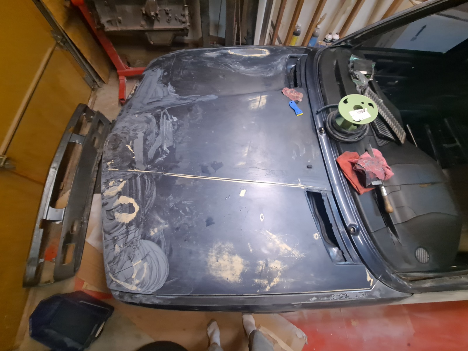
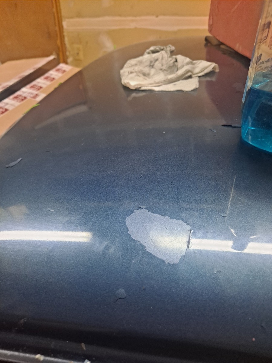
It turns out the hood really had a lot of dings and dents. Here's a picture of what it looked like when I got it.

Image

First wetsanding step of the clearcoat assessing how bad the hood was. It seemed like dings everywhere. After this photo, I got some body filler and tried to fill the dents and then sanded layer by layer to try to get things looking better.

I tried to see if a spare euro valance would fit the car, but it turns out the early 533i valance will not fit the later euro tow hooks. So that valance wouldn't fit afterall and I cannot use it.

Image

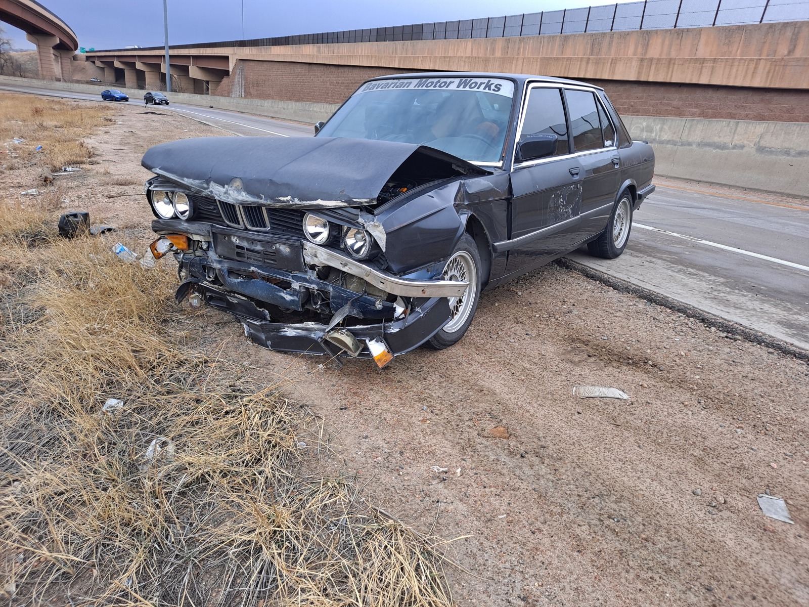
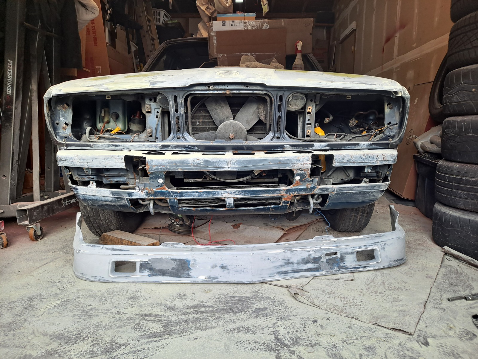
Here's how the other front valance and the Alpina spoiler looked at the crash :(
Image

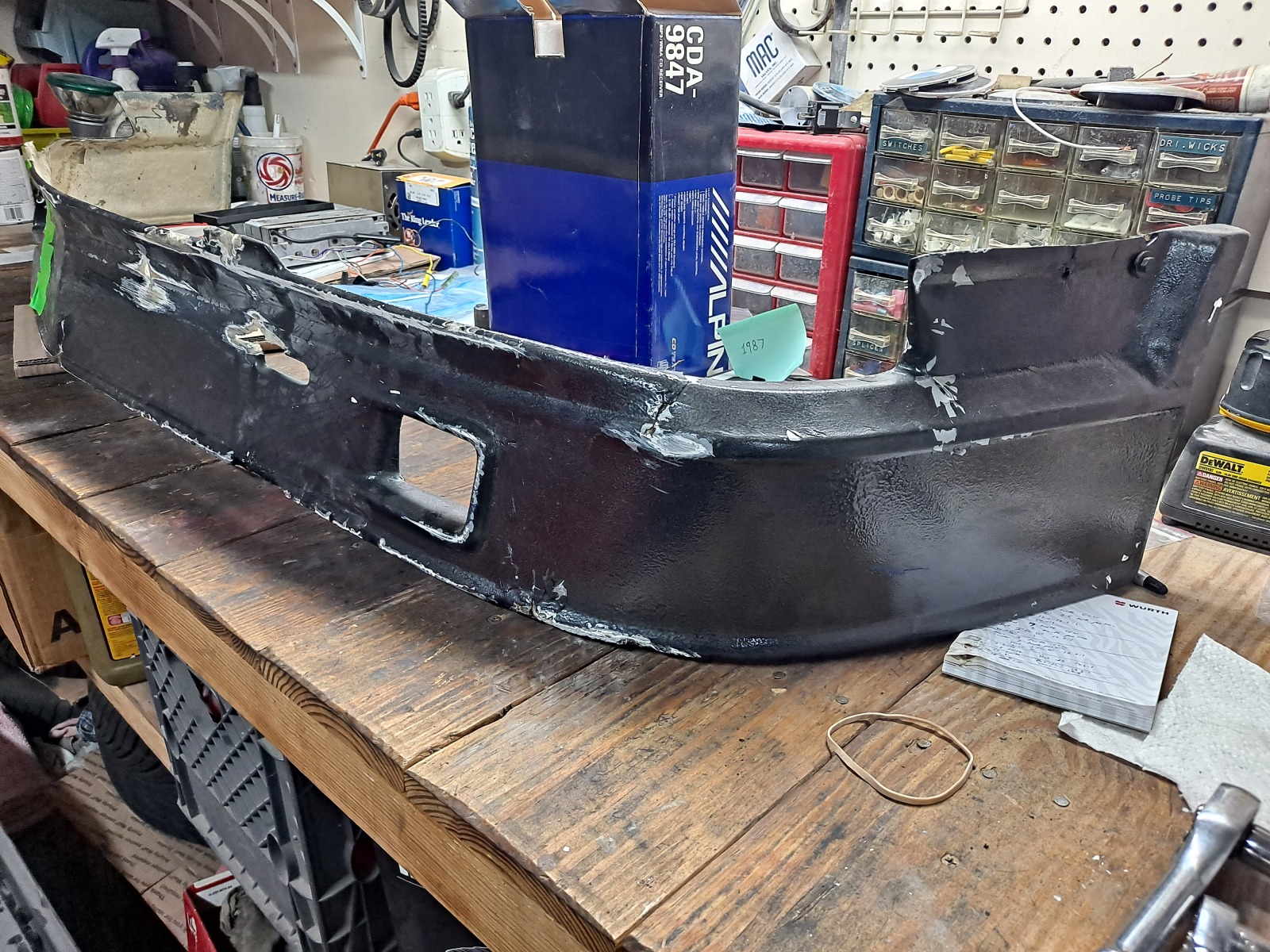
I decided to try my hand at repairing the airdam. This was the first step after trying to get it back toether in one piece to see if anything major was missing.

Image


So I took a few metal rods and a hammer to straighten the existing valance. I spent a couple hours masssaging it into a closer looking shape. I really started to worry that it wouldn't be usable at all, but I wasn't ready to spend for a new valance considering the other parts I need to replace. I sort of realized that it would be covered if I decided to use the Alpina airdam, so it really just needs to be there in place to hold everything up (fogs, turn signals, air dam), and most of it would be covered bu the air dam and bumper.

Eventually, after hammering on it for too long, I tried fitting it onto the car.

It's not perfect, as you can see here, but it was straight enough to mount on the car and I figured maybe good enough to use. You can see the Alpina air dam was starting to look like the correct shape afterall too.
Image

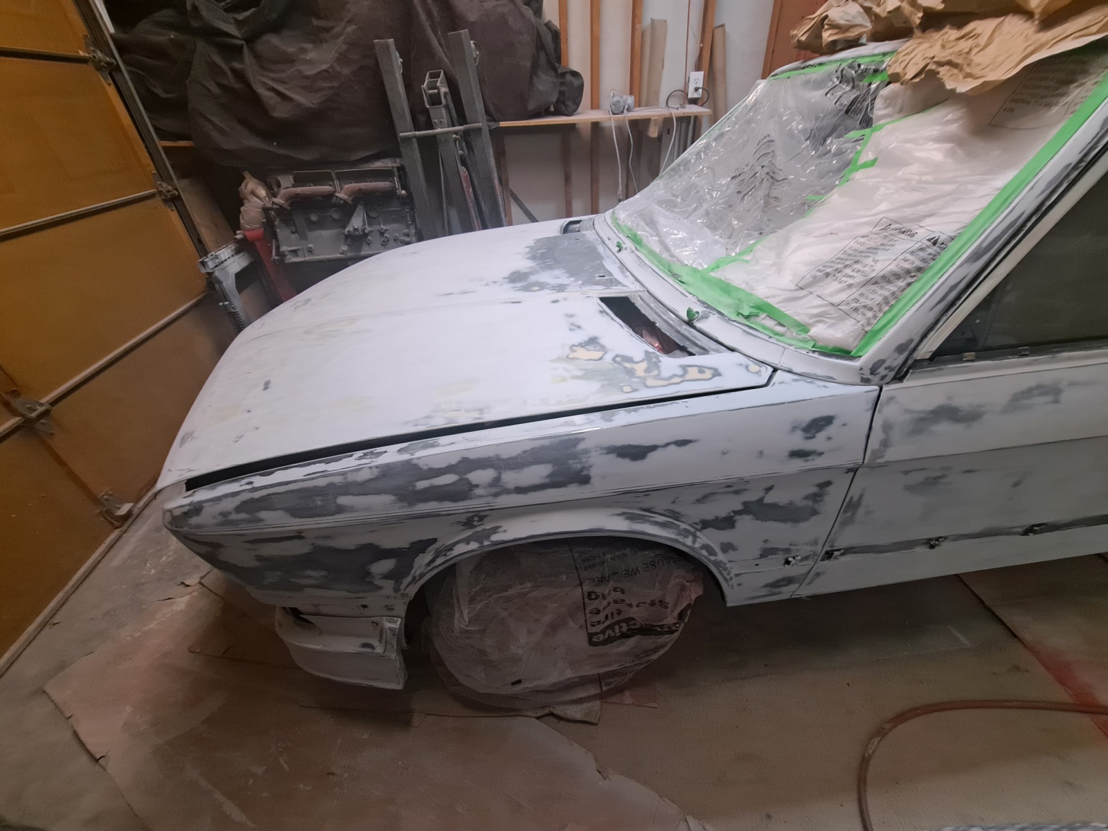
I spent a lot of time working on the pushed in nose and especially the hood, knowing it would be visible and any irregularities would be easily seen. The above photo was pretty close to finished, though I did continue sanding beyond the 320 grit all over.

Interestingly, I found with some paint that I got lifted up that the original Artic blue had been painted over with a darker blue. Here is the photo where you can tell the difference. I tried to lift as much s possible, assuming that that layer might not hold in the future if it was already separating. But it also didn't look like that section had been scuffed or primed. This car definitely had some dings and repair work/paint work.
Image

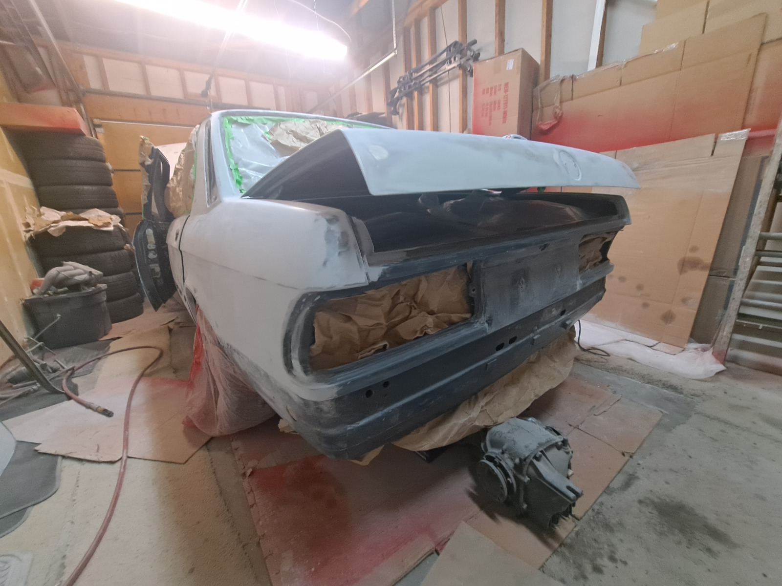
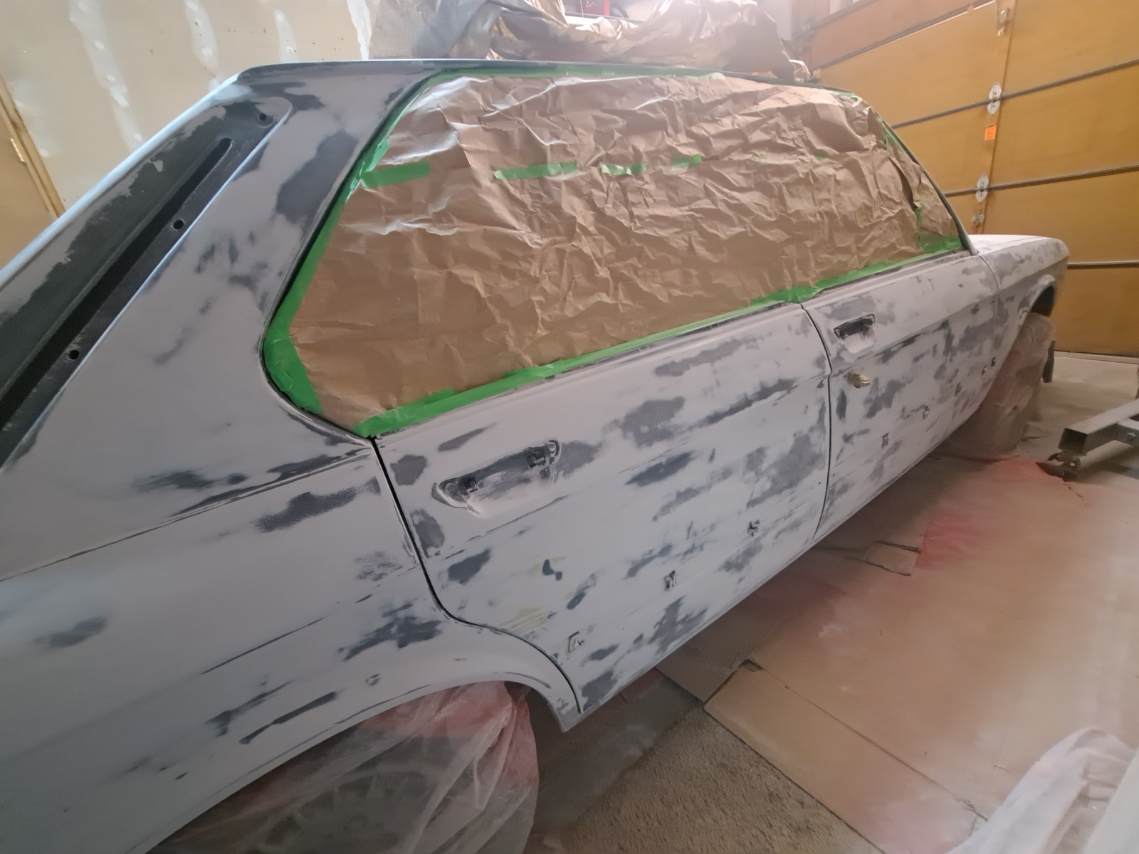
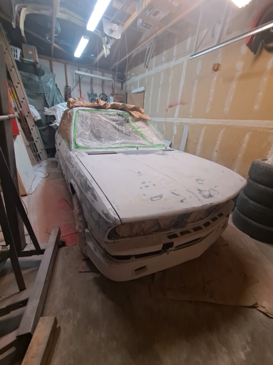
I started sanding everywhere, then masking and priming and more sanding. The weather has been unusually warm here for November, so I decided I would order paint and try a basecoat/clearcoat metallic paint job. I had done single stage enamel in March on the '79 635 and ended up with just enough space to be able to paint the car in my split garage. It has an enclosed area where I can have a door open and then a garage door for airflow. I bought a boxed attic fan for cheap off facebook and it moves enough air to work in the space. I have a siphon feed Binks spray gun from a prior job, and I have 3 small compressors that I can hook together to have 15gallons of air and 4 or 5hp worth of compressors to keep up with air demand. I put the attic fan under the garage door and block off the rest of the space, and the open the doorway and partially open the other side of the garage. It moves a good amount of air, way more than small box fans can move.

Here's how the body was shaping up
Image

Image

And then I mounted the airdam to see if it would fit to the existing valance and new body after my repair efforts
Image

And here with the hood looking reasonable finally

Image

I decided to go with a darker blue, Royal Blue just becaue it is rare and I am sort of on the fence with Artic Blue. I had really liked the darker color of diamondshwarz, so this was a bit of a compromise without having to repaint every door jam and such.

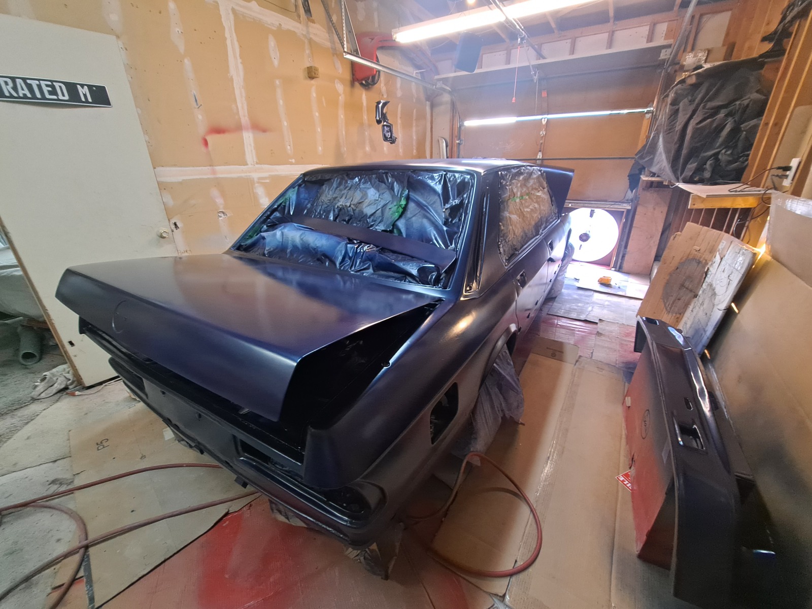
This November has been warmer than I remember in years and I wanted to take advantage of painting it before it got too cold and I'd have to wait until March or April due to winter temperatures. I painted on Wednesday the basecoat in 60-65F temperatures. I used a whole gallon and generally it looked good, but there were a few sanding scratches I started to worry about.
Maybe my conventional spray gun wasn't as efficient as an HVLP, so maybe I could have had better coverage, but overall I had just enough paint.

You can see the fan running and the opposite doorway where air enters from.
Image

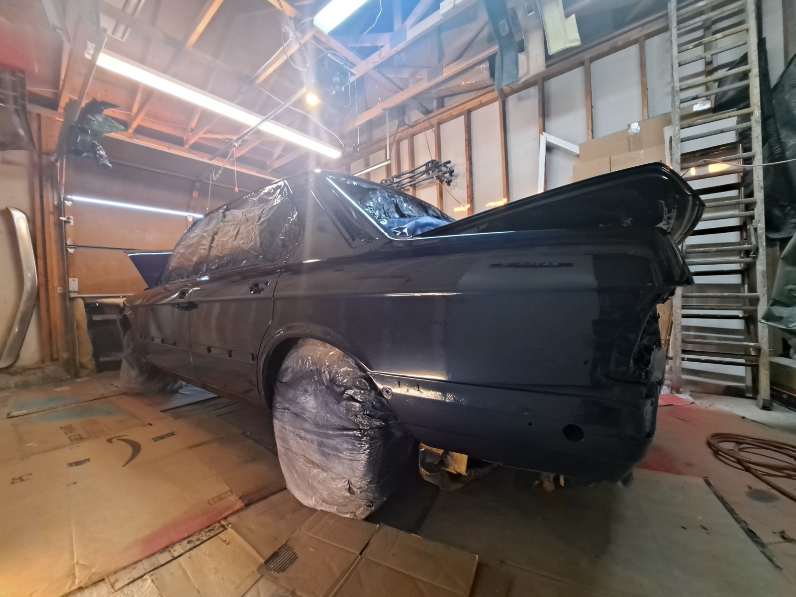
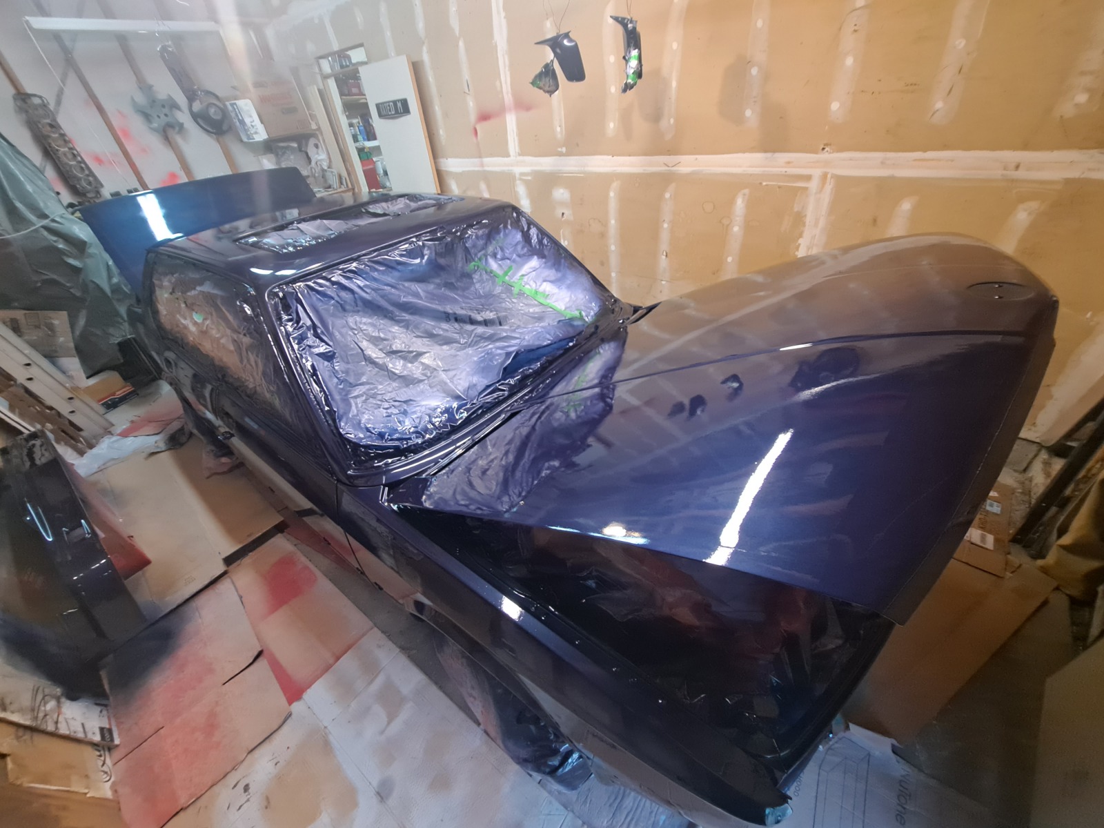
Then, I decided with the weather still looking so good to paint the clearcoat yesterday. I read some say the scratches would show, others say not. I decided to go for it and most of them are not visible. Yes, there are impferfection, but I am also pretty happy with how it was looking! The clear coat after 1 coat was looking more shiny and promising to me!

Image

With 2 coats, I started feeling like it was going to turn out OK for a DIY paintjob. All self taught, so there are some mistakes, but it is satisfying to see the result!

Image

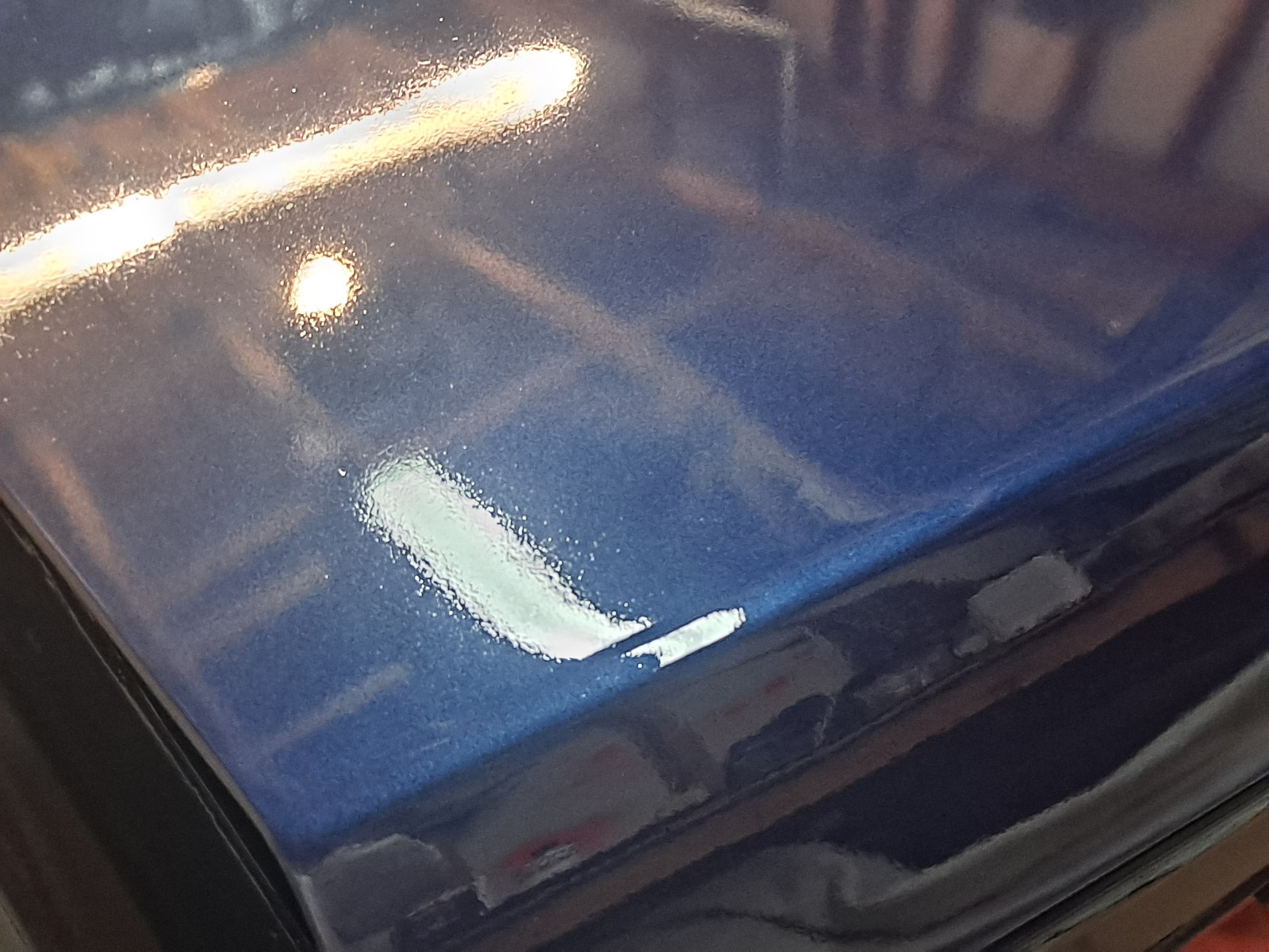
And a close up of the finish as it was drying.

Image

I plan to wetsand just to try to remove some of the imperfections and really get it looking nice. I hope it stays warm enough to continue on this in the upcoming weeks!

Otherwise, I need to install the diff/axles and start taking parts off the 535is to put in this car. The big task with it is to decide exactly what I do with the engine. I can remove the engine from the 535is but need to identify if it is 100% good or if it has any damage at all. Otherwise, I could buy a clutch and build up a spare B35 block/head and g265/6 that I have on the shelf. That might be easiest but I would have to steal the turbo,megasquirt, injectors, oil pan and other bits from the 535is anyway, making it non driveable. Also It has the B32 lightweight flywheel and I only have a 535i flywheel on the shelf.

I'm not sure how many people are following this, , but I figured you deserved an update and I hope you enjoy seeing that there is more to the story!
 

Re: Homebrew Turbo e28 (ex Callaway) - 2025 Update

Posted: Nov 18, 2025 11:25 PM
by turbodan
Doing great work. 

Re: Homebrew Turbo e28 (ex Callaway) - 2025 Update

Posted: Nov 19, 2025 11:49 AM
by austin8753
nice job. keep up the good progress.

Re: Homebrew Turbo e28 (ex Callaway) - 2025 Update

Posted: Nov 29, 2025 10:40 PM
by tschultz
Thanks for the encouragement.

So I started wetsanding the fresh paint, though I haven't had as much spare time and the garage is now getting a bit cold, so I am making slow progress on that step. Since it has a clear coat, it seems like I will be able to sand and then buff out some of the orange peel and imperfections. Overall it looks pretty good, even though there are a few runs and fish eye spots, they are mostly coming out. Lots more work to do, but it is encouragingthat it may turn out looking decently nice.
 
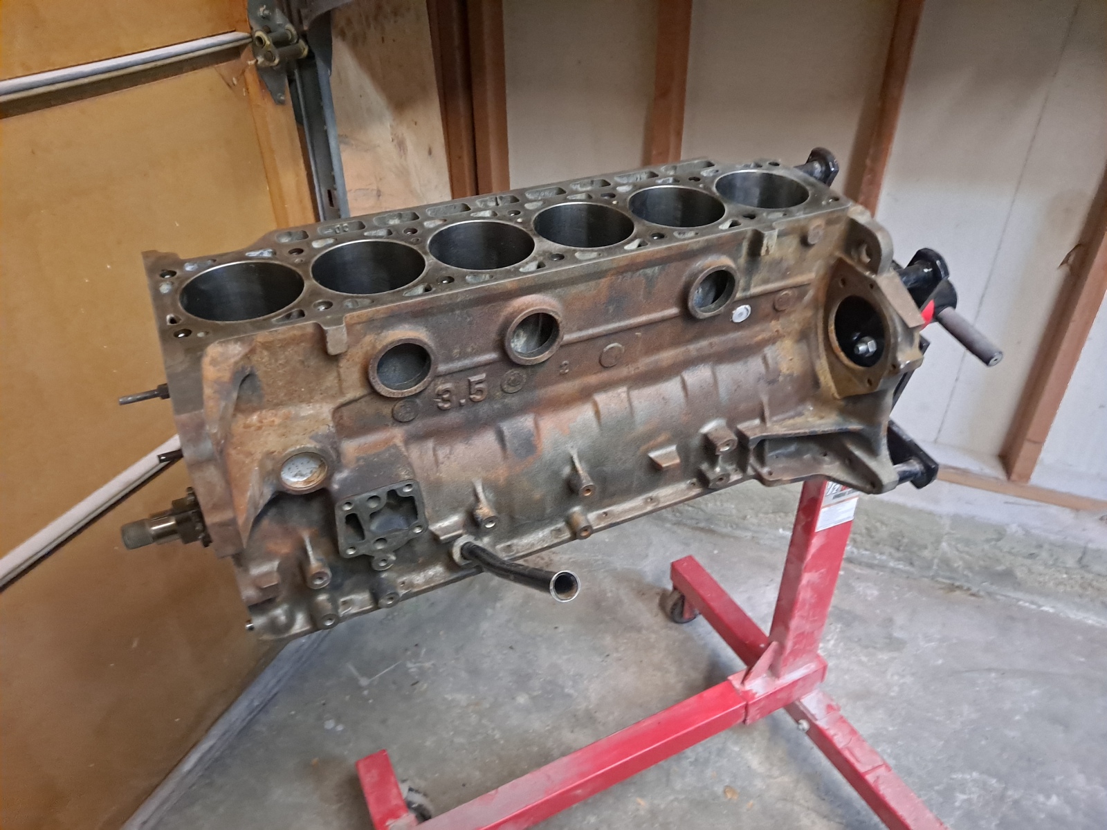
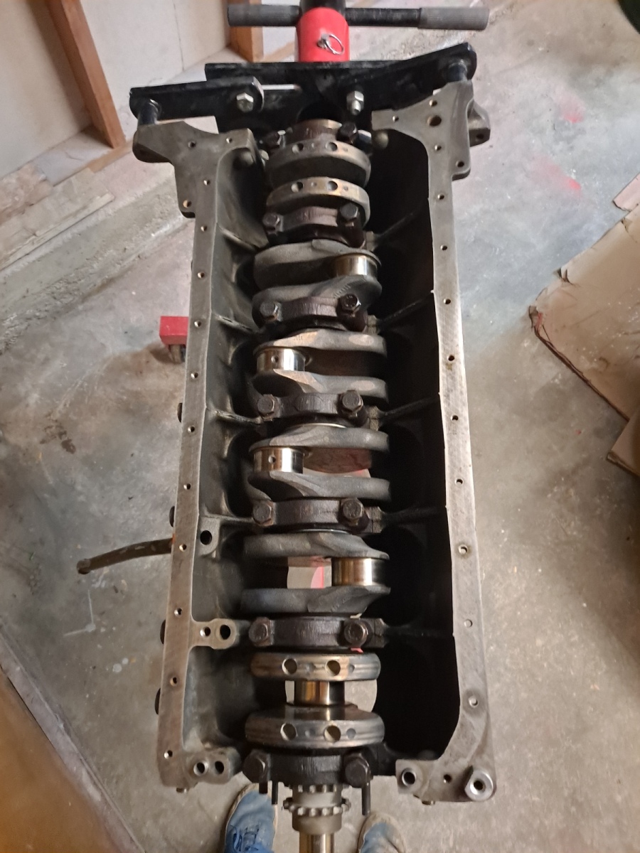
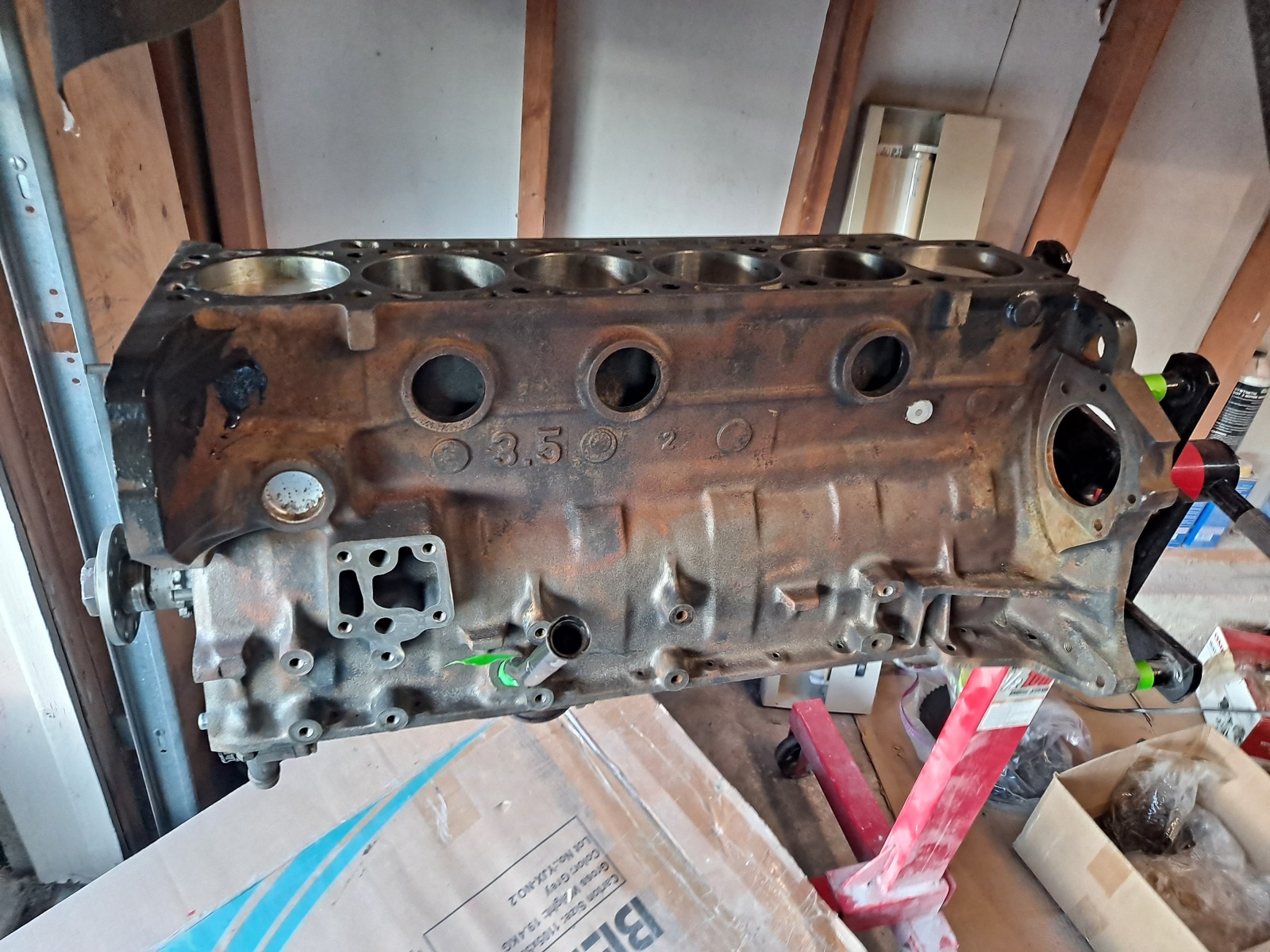
I got my spare B35 engine block from my brother's place over the weekend. He has had it for a year while I was busy with other things, including the last iteration of the 535is and engine build. This block is an overbored .020 '88 E32 735i block. So I have the oil pan/pump and oil filter housing that I need to decide which version of parts to install. Likely e28 pan/pump from the engine still in the 535is since it has the oil pan drain.

Image
I think I will paint the block and make it look a bit nicer before continuing much more reassembly.

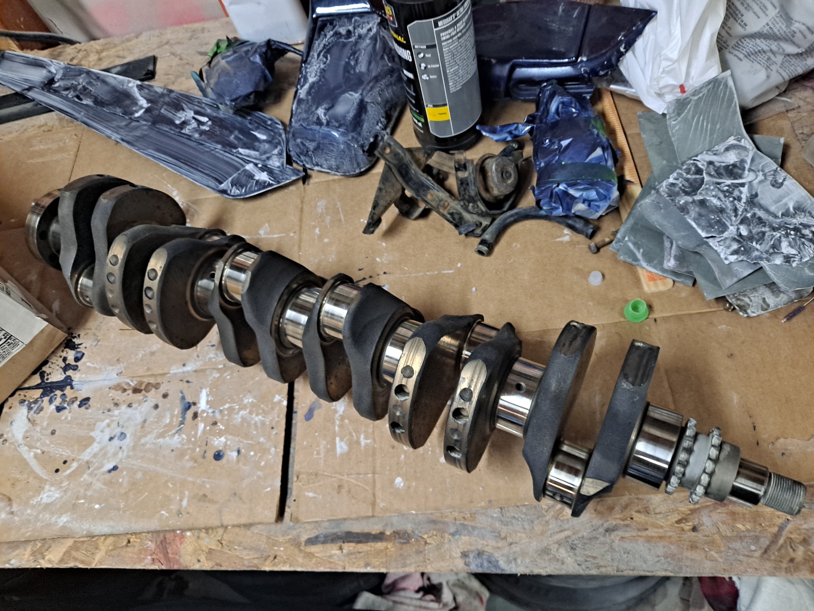
I measured the crank shaft and everything is in spec! So standard bearings were ordered and delvered this week.

Image

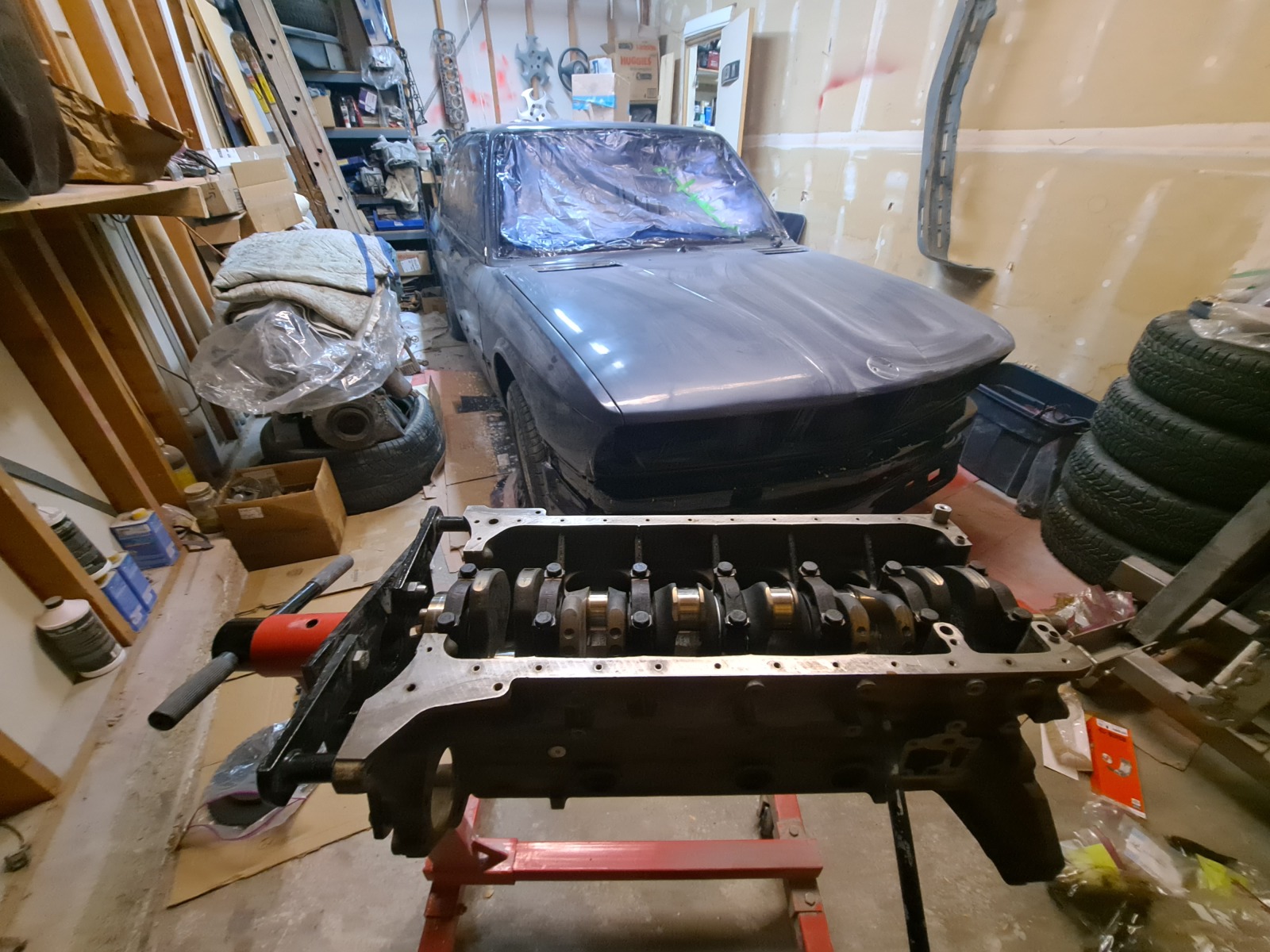
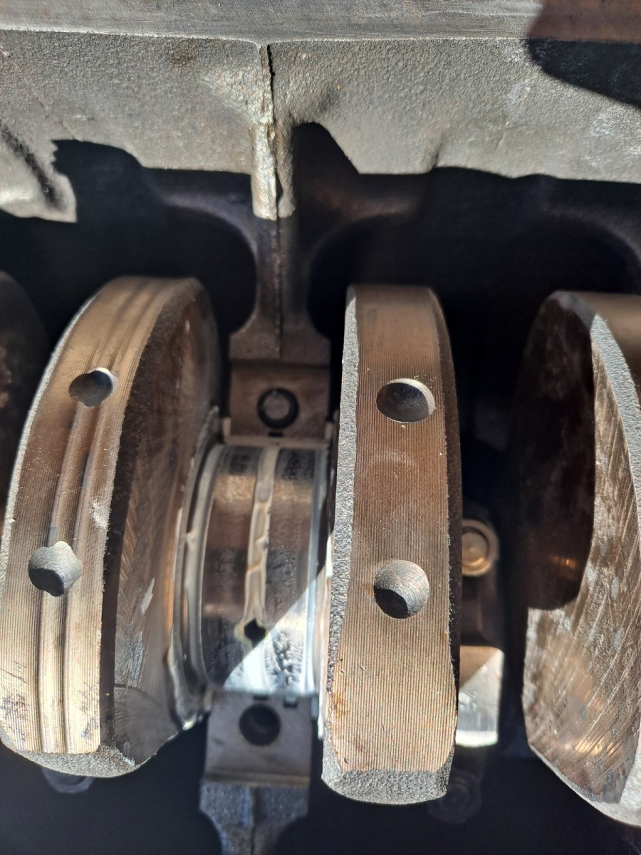
I installed the crankshaft last night with the GLYCO main bearings. I decided not to buy King or ITM bearings and I didn't want to wait 6 weeks for authentic BMW main bearings. They are back in  stock places which wasn't the case 18-24 months  ago.
Image

Here is how the car is looking and my workspace, still very much a work in process. The covered engine is the old B34 that has some blowby that came out of the 633CSI and my friends car originally back in ~2016, but with a good ~5k mile cylinder head.
Image

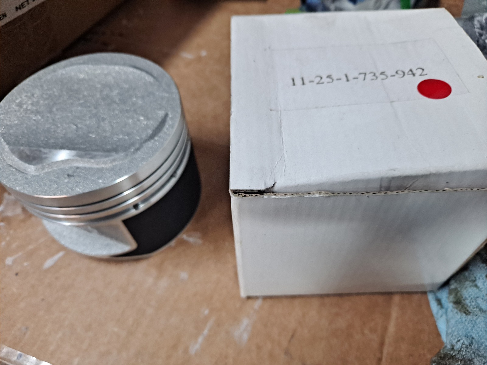
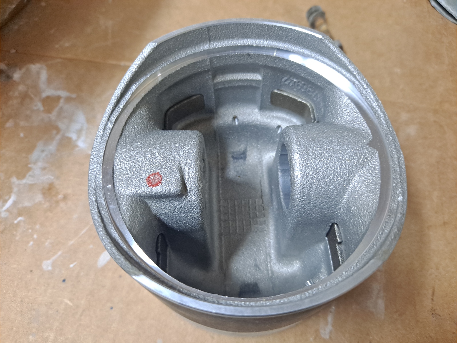
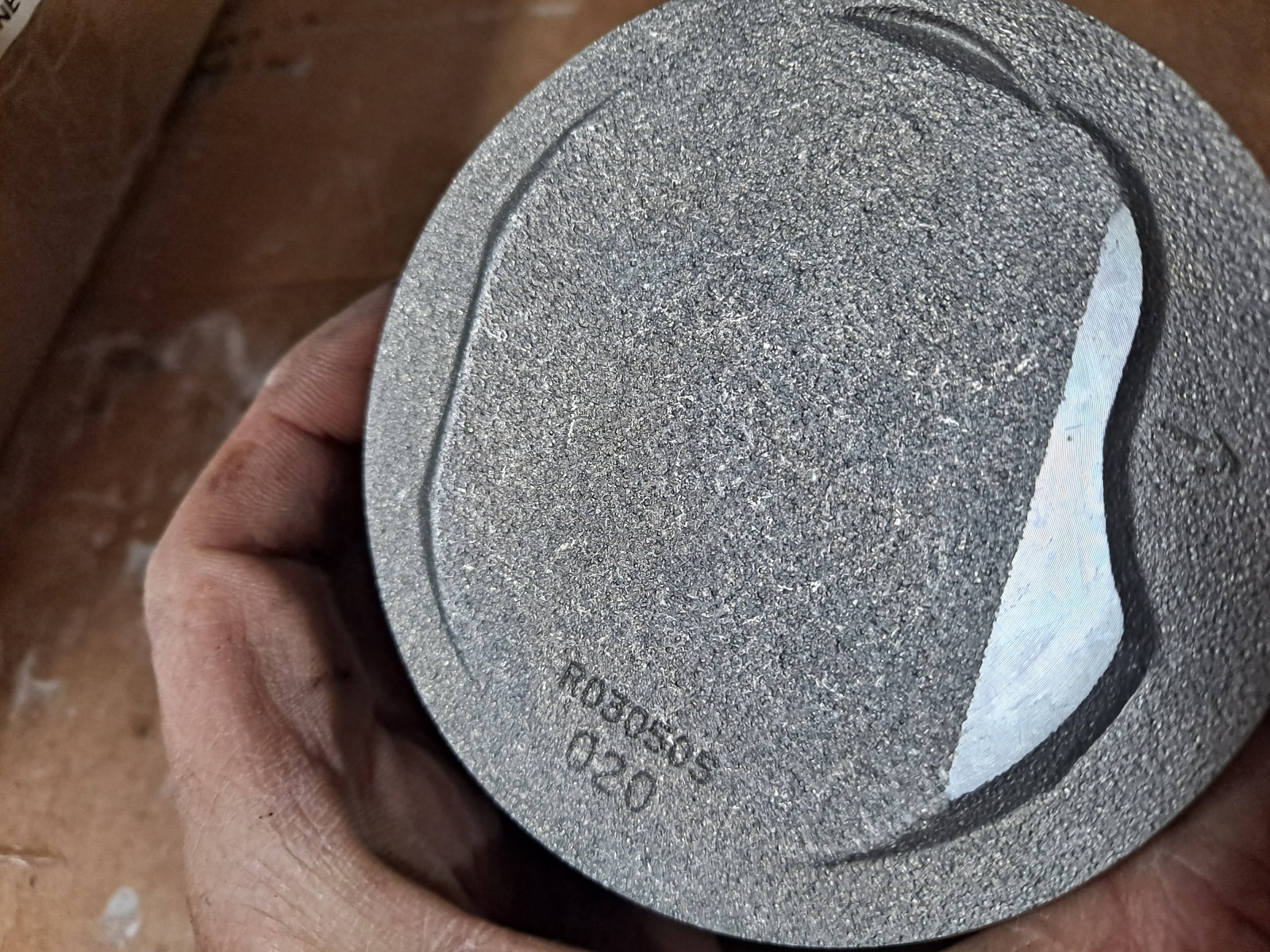
Here are the oversize pistons which will be able to go in soon I think. This part number is now suddenly NLA, so I am glad I got them as a set with the block.

Image
Image

Image

More progress to come, I need to swap some parts from the 535is and just continue moving forward before I can pull the turbo, oil pan and other bits from the 535is. I have a rebuilt B35 cylinder head that will go on to complete the build.


I am not sure what to do about the intercooler right now. I don't want to spend a ton of money but am casually contemplating some changes like a flipped throttle body (not sure I will do that), B35 oil filter housing, B34 factory oil cooler or similar, placement and type of intercooler W/A or A/A. I don't have a clear direction on what I want to do because I know fitting it under the euro front end will be tight, especially with B34 oil cooler placement.

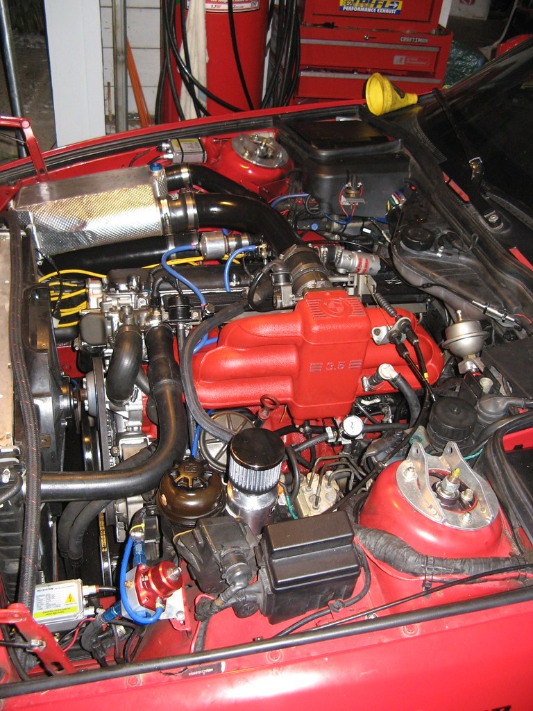
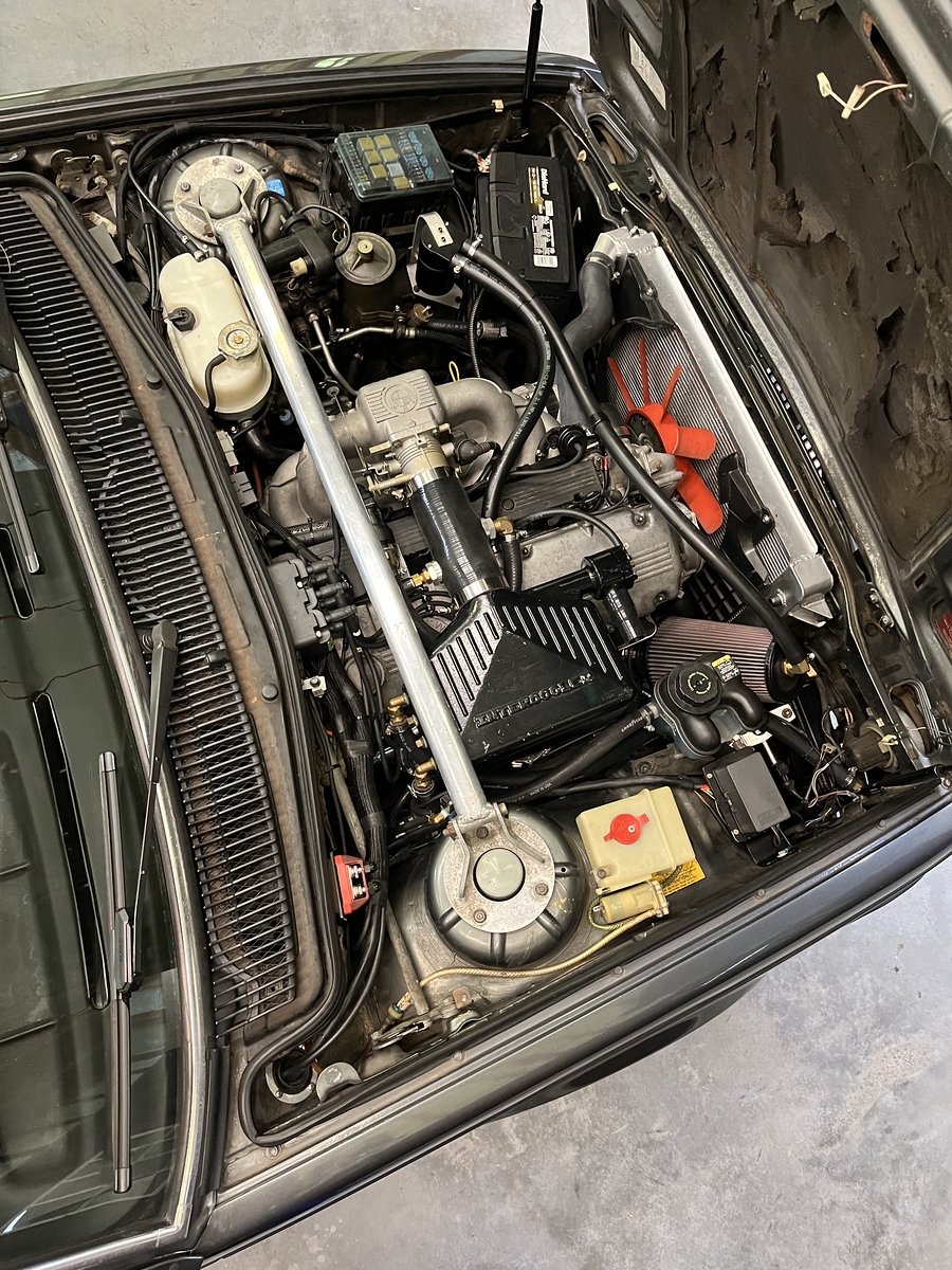
Oh and here's some motivation, maybe a similar look I am going for:
Image

Image

Image


I don't want to cut anywhere in the sheet metal to make these pieces fit...I like to keep reversibility just for that option. 

Any thoughts or ideas from  people who might do something different on their own build?

Re: Homebrew Turbo e28 (ex Callaway) - 2025 Update

Posted: Nov 30, 2025 12:42 PM
by MyE21
You have followers on your project!

sorry about the incident, but it looks like you’re bouncing back.

Anyway, please keep up the updates, they are appreciated!

Re: Homebrew Turbo e28 (ex Callaway) - 2025 Update

Posted: Dec 11, 2025 1:43 PM
by tschultz
Thanks for all the positivity guys.

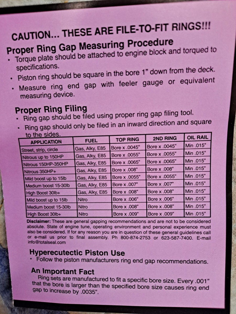
I got started measuring piston ring gaps in each cylinder this week. They are Hastings Rings which did not come with install documentation on these clearances. After measuring, I got approximately .017" for the top ring and .015" for the 2nd ring.

I got some Total Seal rings and they came with the following specification:
Image
Below I am quoting mye28 content in image format:
Image
Image
From my research, 2nd ring gap should usually be larger for turbo application.. Here is one user here saying a rule of thumb in his builds:
Image
My bore size: 92.50mm / 3.642"
3.642" * .0055 = .020"
3.642" * .0065 = .024*
3.642" * .0075 = .027"

I know the Hastings Rings were consistent across all measurements, but I have done some research and it suggests that a smaller gap may not be as critical as some people suggest. Especially in turbo applications, a larger gap is important so as to not run into the issue of the ends touching and resulting in failure and some kind of engine damage.

So I am thinking I want to keep the top rings, as provided (.017"), and then open the 2nd rings to .022-.024". Any thoughts or experience with this? I thought that my last/current engine had .018-.020" on the 2nd ring, but I will need to double check if I wrote it down somewhere.

I plan to paint the block soon here also, maybe this weekend. Little by little we will continue.


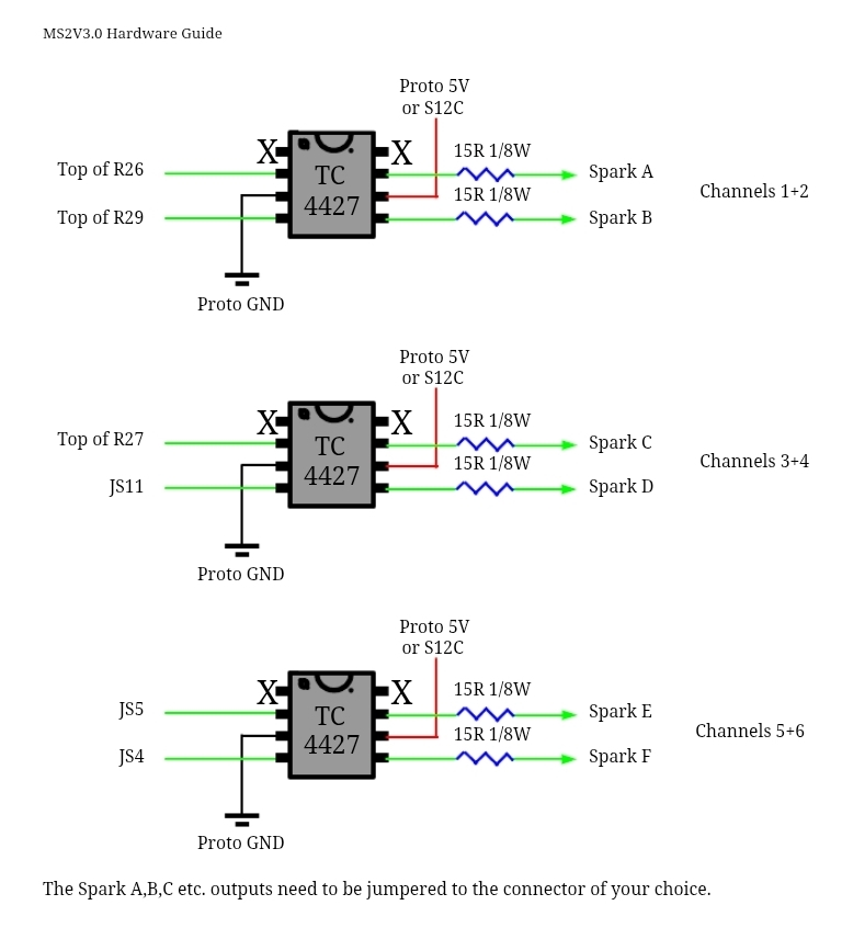
In the mean time, I was researching Wasted Spark with my spare MS2 unit. It is V3.0 and has these T4427 modules that need to be finished soldered in that would work with logic level coils. I am trying to decide if I might want to try this setup or what.
Basically I would use  them to send the fire signal for 3 coils in a wasted spark setup, or 6 (3 tc4427) with 6 coils in sequential, though I am not sure that is necessary. I have room on my prototype board to do it on either V3.0 ms2 setup if I wanted...

Image

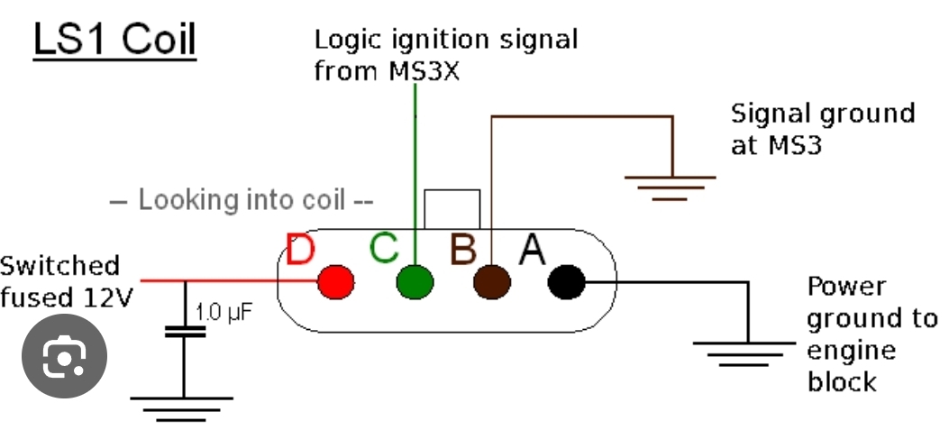
Wiring looks to be fairly simple with the 3 outputs of these chips going to the individual coils, with 2 hooked together for wasted setup. 3 outputs, and then I just need to make sure that each coil has power and ground hooked up properly.

Image

To suit this setup, I bought ACDelco chevrolet GM LS coils D581 which are supposed to be quite good. I got 8 for less than $100. It looks like this is the setup Jake uses for M20 turbo at classic daily. They are big coils and sort of heavy, but maybe I could play with their mounting location when I look at adjusting my intercooler piping setup. Below is his photo, mounted on an M20.
Image

My intake elbow of aluminum may or may not  allow this position on the valve cover^^
More research required on this topic also.


Maybe I will do clearcoat wet sanding this weekend if warm enough to be in the garage for a few hours.

Re: Homebrew Turbo e28 (ex Callaway) - 2025 Update

Posted: Dec 11, 2025 9:26 PM
by turbodan
Of course I must preface this advice with a disclaimer that I may well have my head up my ass, but I've never increased ring gap in a turbo motor.  Not much harm in it but even up to 25 pounds of boost and 7200 RPM I've never had a problem.  The rationale is that turbo motors generate additional heat and require looser clearances.  I would contend that thermal input is proportional to RPM primarily and that boost in itself doesn't necessarily and substantially increase temperatures in the piston crown and upper cylinder, especially if your AFR and ignition advance is appropriate.

Re: Homebrew Turbo e28 (ex Callaway) - 2025 Update

Posted: Dec 15, 2025 9:43 PM
by tschultz
Thanks for the input Dan. I checked and some research online suggests slightly bigger 2nd gaps are better for sealing and to prevent some sort of flutter. Basically, the gaps are very close to the oem spec, so I just feel better knowing that the 2nd ring gap is not tighter than the top.

Started painting the block. It wasn't bad or super rusty before, but I liked the block being painted previously, so I decided to use the same Rustoleum oil based paint. 

Image

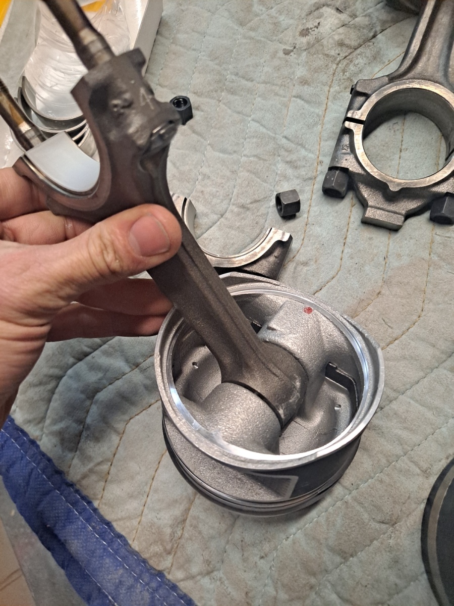
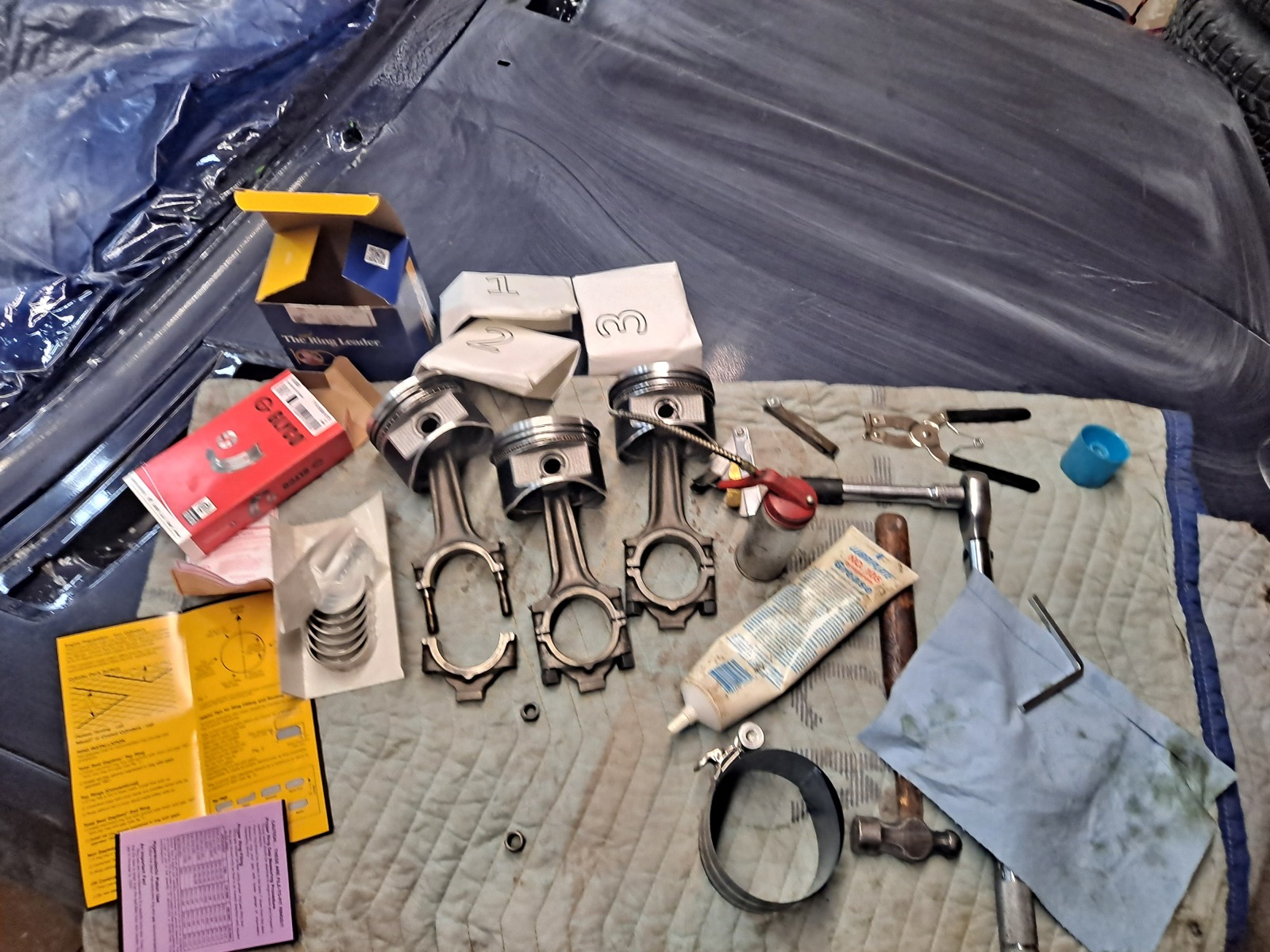
Here's a photo of the parts going together. Connecting rods and pistons:
Image

Image

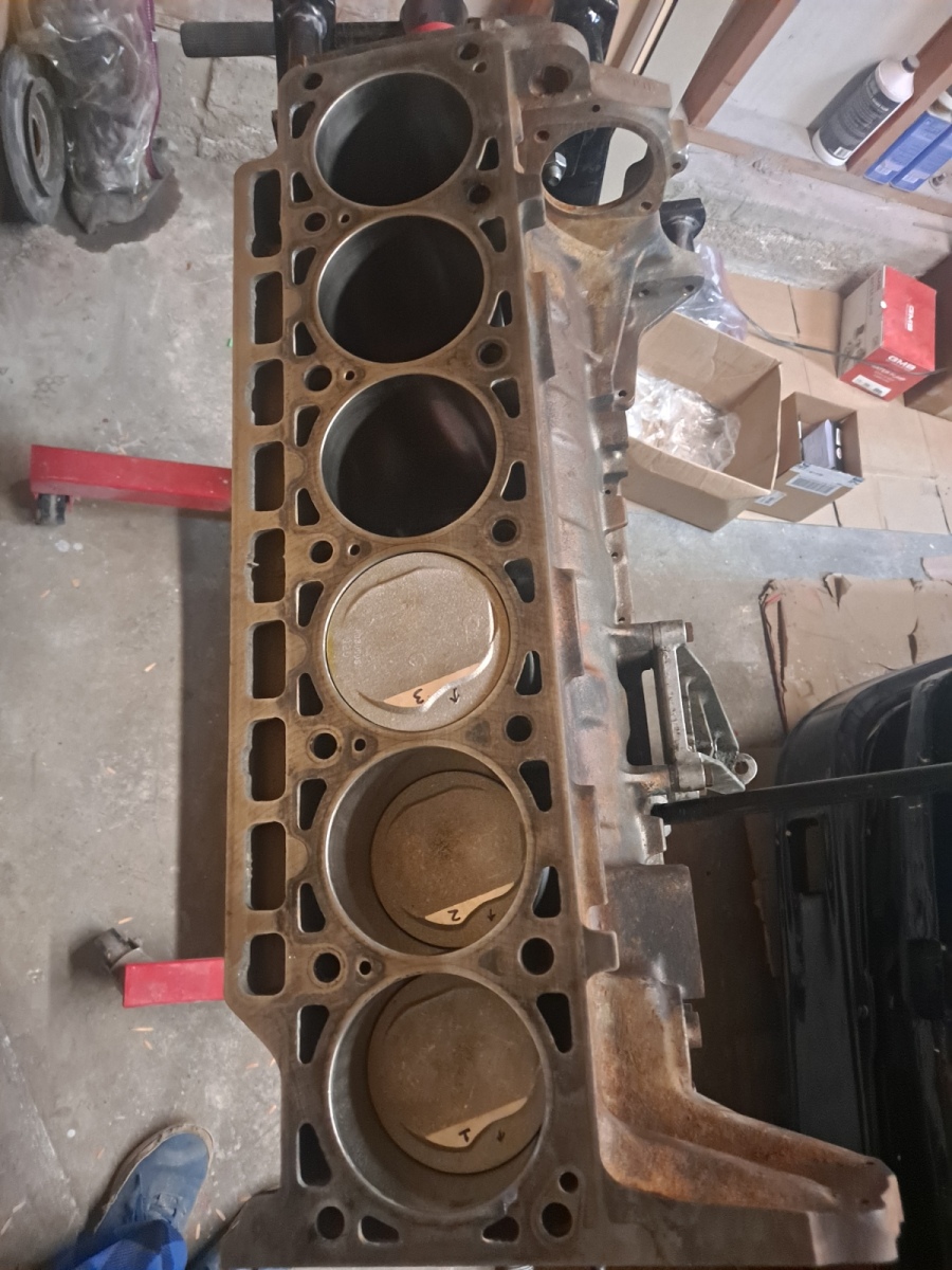
Pistons 1-3 in place
Image

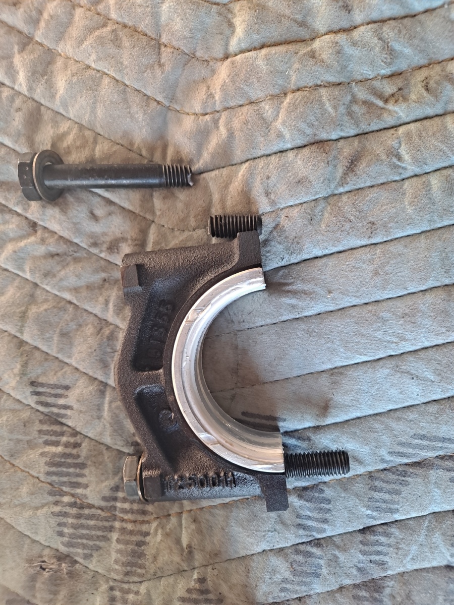
I was installing the oil pump and torquing the main middle thrust bearing cap and suddenly the bolt kept turning. I should have known better, but it snapped/sheared after another soft feeling 1/2 turn. I was super frustrated until I started turning it and realized that the end was still free to turn inside the block. So I got it out and happened to have a few spare bolts that I could replace.

Image
Image

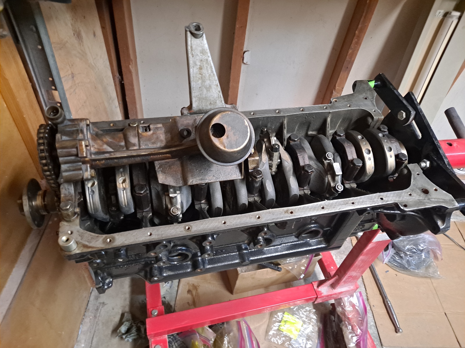
Here is the oil pump installed. This is B34, but I do have B35 sprocket and tensioner setup. Is the B35 oil pump tensioner better one to use? Any experience with that? I read I can switch the pick up and use the B34 pickup with B35 pump and parts which may have a better relief valve. Any opinions here would be appreciated since I have both on hand at the moment.
Oh and you can see the block is now painted even though it isn;t the best image.
Image

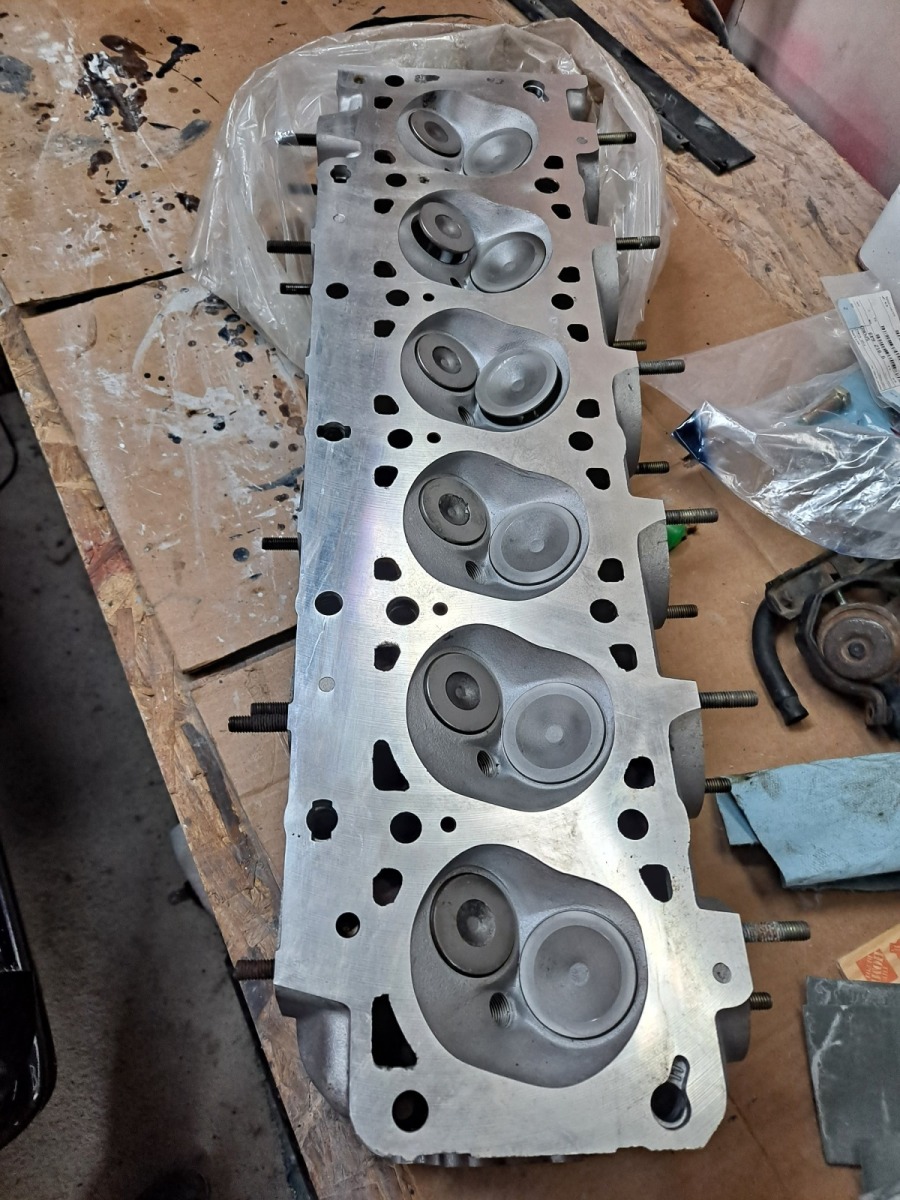
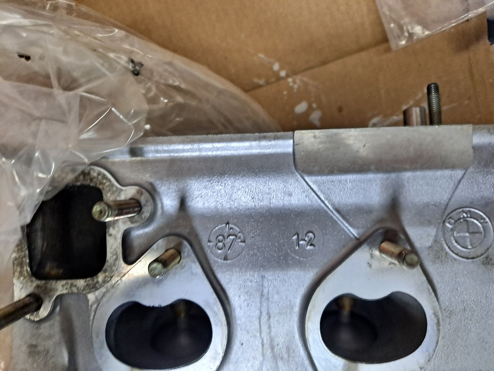
Here is a photo of the cylinder head. It was machined and rebuilt and is a match to this block, 1987 production.
Image

Image

More to come, but I do need to drill out an exhaust stud that is snapped off on the exhaust side... Mayeb I can fix that and then assemble the front timing cover and cylinder head in the next few weeks-- the weather has been warm enough lately to work in the garage!

Re: Homebrew Turbo e28 (ex Callaway) - 2025 Update

Posted: Dec 16, 2025 4:11 AM
by Tiit
Looking good.Thank you for sharing.

Re: Homebrew Turbo e28 (ex Callaway) - 2025 Update

Posted: Jan 04, 2026 11:33 PM
by tschultz
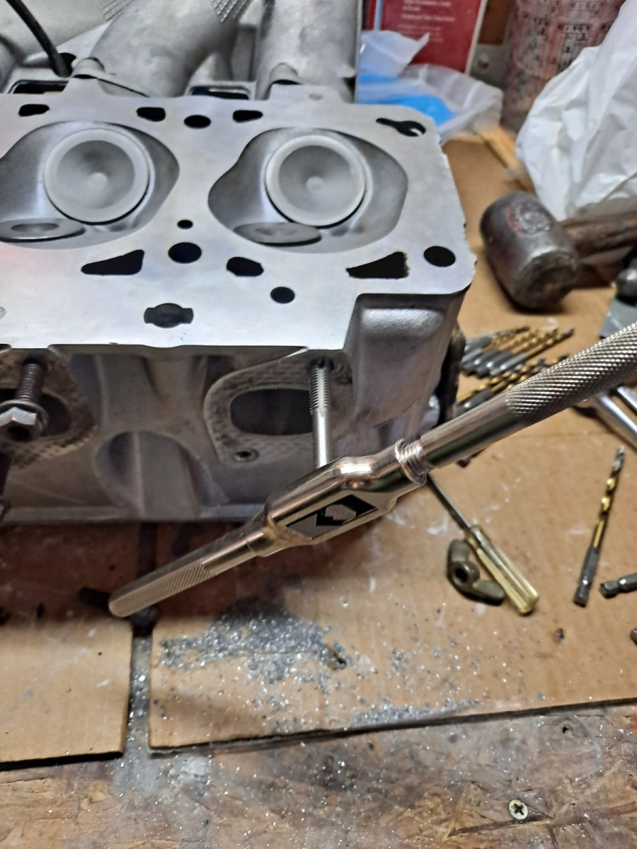
So I spent some time on the car with the warm weather. I had found a broken exhaust stud and was able to drill it and retap it manually in my garage. A spare exhaust manifld fits up. An extractor set didn't work to remove it, I drilled with slightly larger drill bit sizes up to approxiately 1/4" and then I was able to retap the threads.

Image


Not a ton of photos of it, but I decided to go for the B35 oil pump sprocket, shorter chain and a new tensioner setup. Here is how it looks and it should give some additional start up pressure that otherwise gets taken by the turbo feed.

Image

I figure the main relief valve limits the upper end,but lower rpm pressure that is higher is only a positive. The tensioner also means the chain won't have any slack or need future shims.A small nylon spacer is used to hold the tensioner metal leg and I had that from the original engine disassembly, along with the mounting pin that holds the tensioner (Earlier m30's didn't have it).

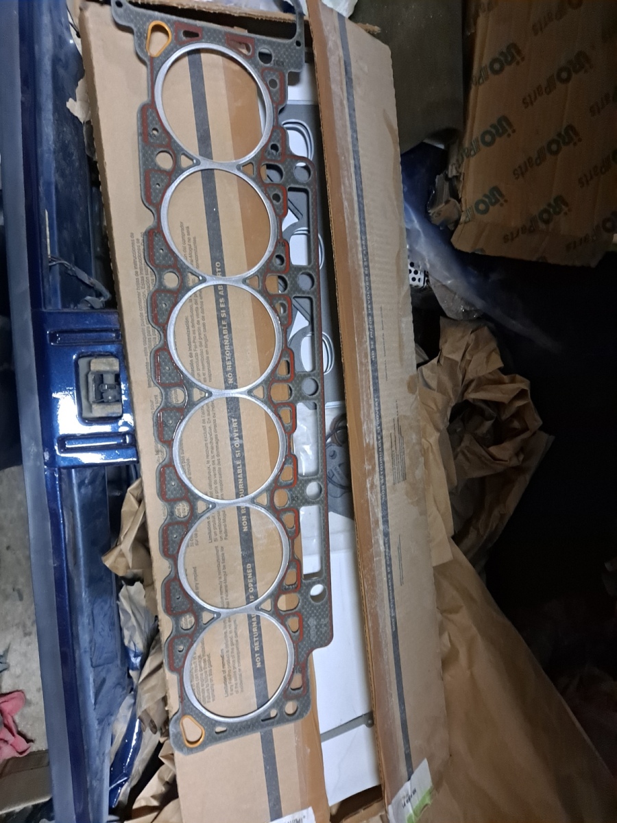
This is actually a Goetze gasket, (Fel Pro kit) which looks more substantial than the Elring version I have used many times now. I hope it is a better choice for boost.

Image

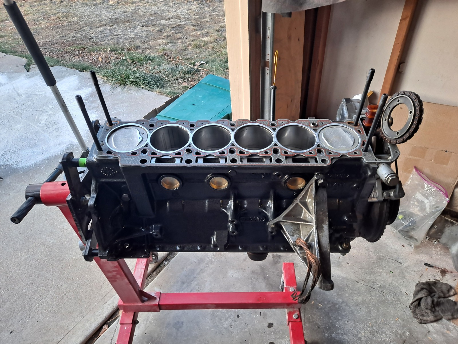
Feeze plugs tapped in to place and the HG sitting on there patiently:
Image

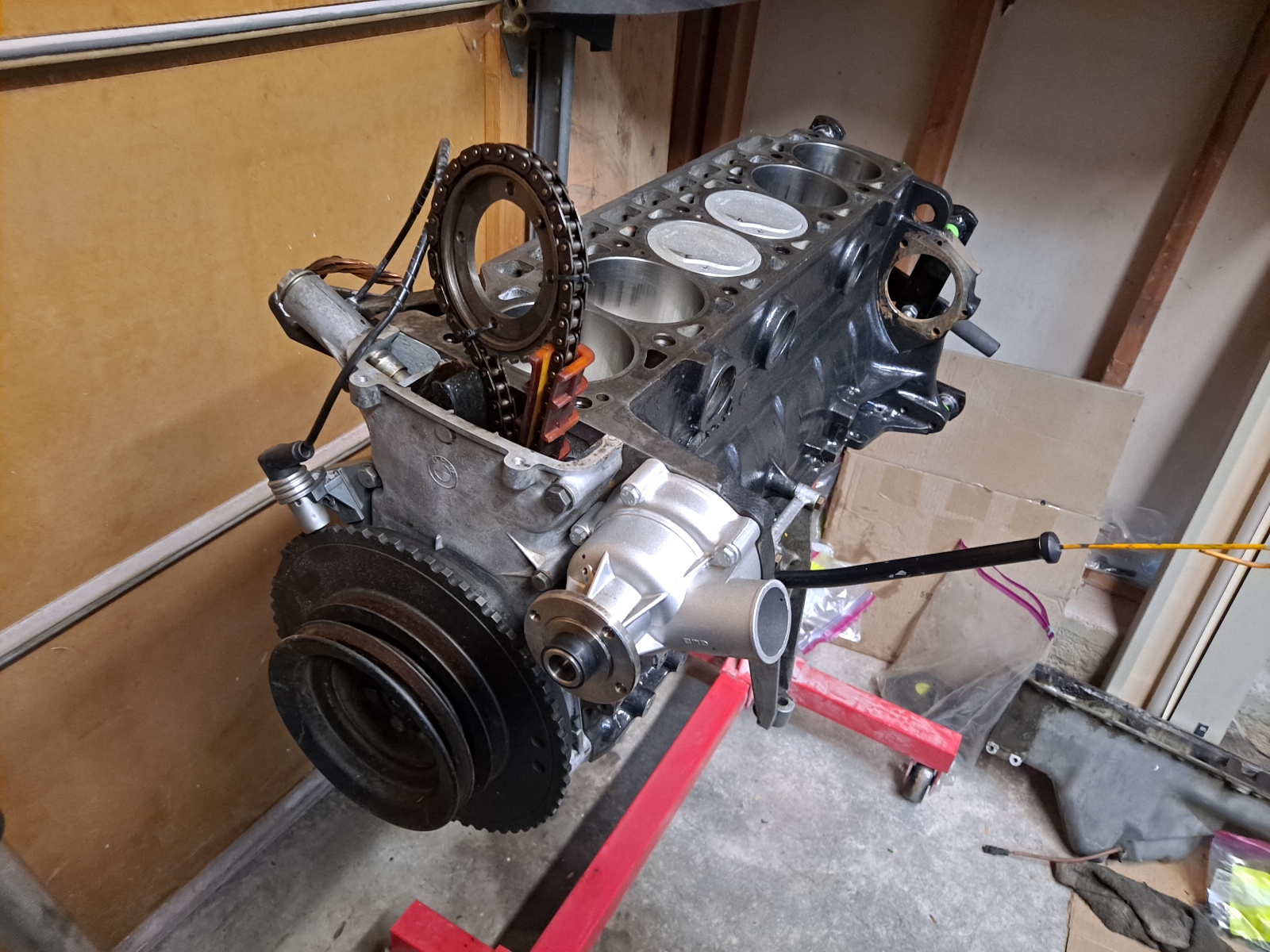
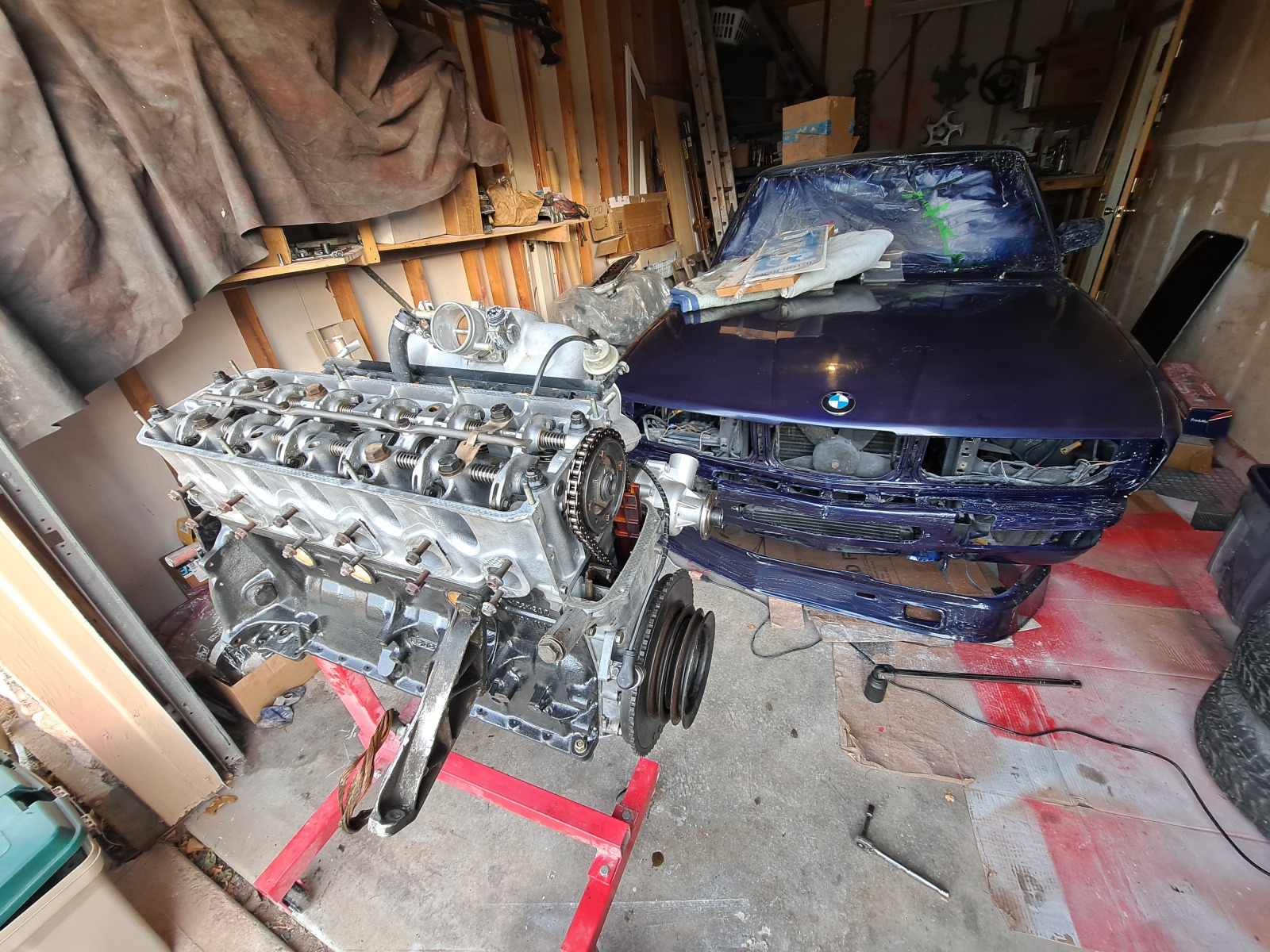
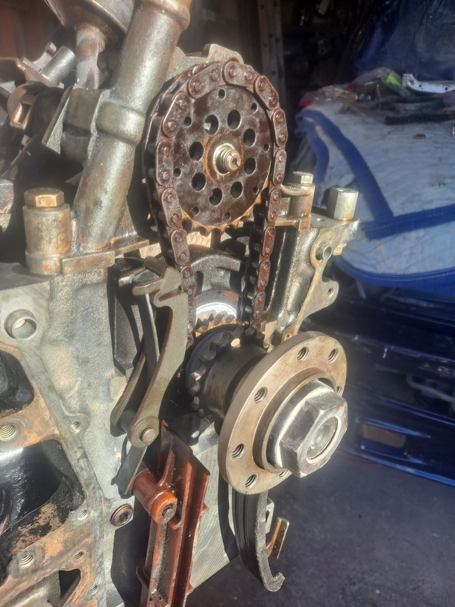
I got the chain on and tensioner and timing cover back together. I had to remove the main crank nut after this picture because I didn't have the tensioner against the main guide properly... But the same combination of tow straps, vehicle tow hooks, engine stand and floor jack allowed me to both remove and reinstall/torque the jesus nut.

Image

I dropped the head on, thanks to my wife for helping me lift it on carefully. Other ARP studs will go on eventually but they are still in the 535is at the moment. I guess you can see the nose of my paint job poking out here and the new (used) BMW emblem.
Image

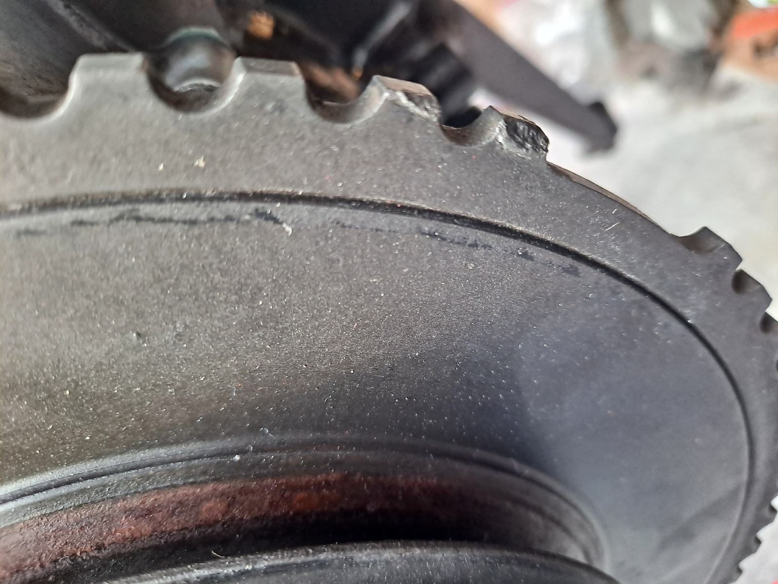
All spins nicely, but I did notice that the B35 harmonic balancer I got with this engine has some scrapes and damage on 2 or so of the teeth. They aren't totally square. I am thinking I will remove and put my 'good' one on this engine just in case it creates some rpm issues.

Image


I need to torque the head bolts on and do a valve adjustment, along with change injectors and oil pan. But I will drop it into the chassis to free some space to pull the other engine and then steal the other parts (power steering pump, alternator, oil filter housing).

More to come later, all depending on the weather and free time!

Re: Homebrew Turbo e28 (ex Callaway) - 2025 Update

Posted: Jan 05, 2026 3:15 PM
by turbodan
This weather has been outstanding. Supposed to take a turn mid-week. Make hay while the sun shines.

Re: Homebrew Turbo e28 (ex Callaway) - 2025 Update

Posted: Jan 09, 2026 7:14 PM
by Tiit
I bet that balancer could be repaired easily. Quick weld and grind down and done. 

Re: Homebrew Turbo e28 (ex Callaway) - 2025 Update

Posted: Feb 16, 2026 6:49 PM
by tschultz
Rebuilt OEM CV axle half shafts were installed, along with Diff (3.46LSD) and 528e diff mount. One half shaft was seized up and I had to disassemble it, but now they are rotating smoothly and freshly greased. I ordered some bolts because the ones I had were the wrong lengths and were too short (2-3 threads) or too long (almost touching through the back side). Got that all squared away.

I had an international business trip in January so it interrupted some work. But I did a bit of wetsanding, still lots to go unfortnately for getting the clear looking more smooth.

I installed the cylinder head, timing cover and intake, so now it looks like an engine, though it still isn't totally compelete yet. I also swapped the harmonic balancer just to be sure that I have a good one on the engine.

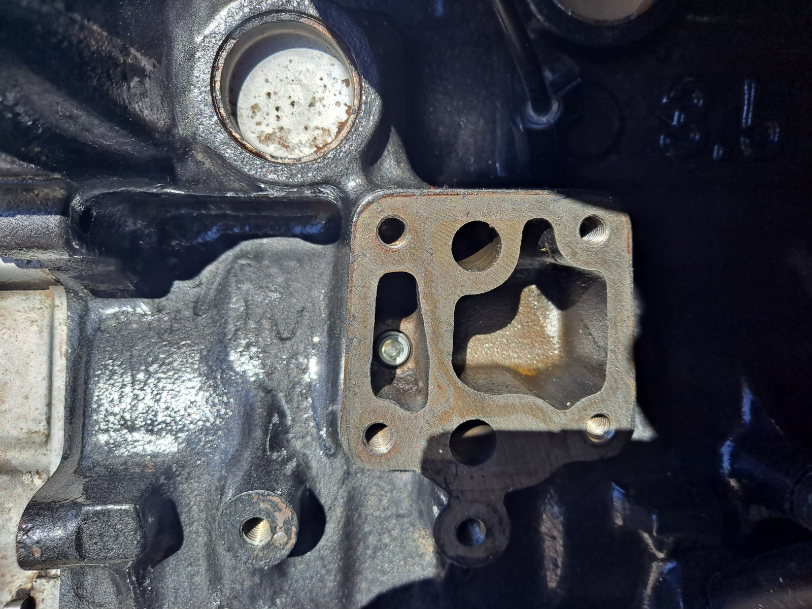
I did finally find an M10x1 DIN plug for the B35 block. This will allow use of the B34 oil filter housing.
Image


 I am trying to decide if I will use the existing housing from the 535is or use an oil cooler housing that I have on hand. If I keep the oil cooler housing, I can obviously run the oil coole,r but I need to rethinkg the intercooler and piping. This is a big question so I am waiting to decide if I really want to redo piping and all of the details related to the intercooler.

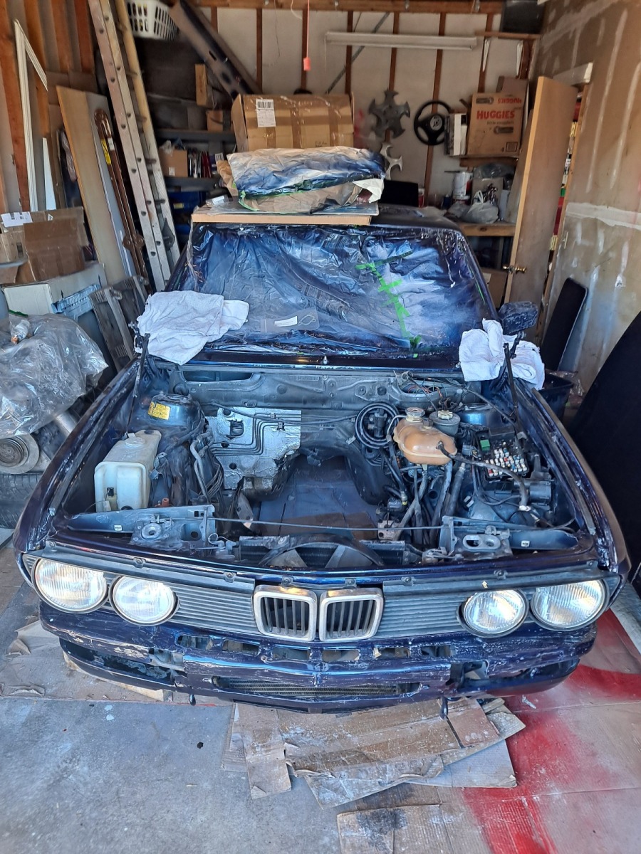
A while back, I did install euro headlights on the car and now it sort of looks like a car again. I have to rewire the euro spec wiring and bring it back to stock, but it looks pretty straight forward. Here you see how it all looks, though I did take off the airdam. I need euro fog light housings in order to install my fog lights, but maybe I can salvage the ones that got taken out in the wreck....
Image


This week, I got the engine sitting in the car. I am missing the correct passenger motor mounting arm, but I have it sitting in posiiton so I can use the other space in my garage and engine stand the pull the engine from the 535is. Maybe that can happen in a month or so. I also need to swap the oil pan, but I put an old one in place during the engine install to protect the oil pump. 

I found the steering box bracket was cracked and broken, so I ordered an MWrench fix and plan to install that soon.


Next up is really taking the old engine out of the 535is and harvesting the good bits: turbo, turbo manifold, clutch, flywheel, oil pan, ARP head studs, injectors, along with alternator, starter and transmission. At that point, I wil lput the B34 back in the 535is to try to keep it 'running' in B34 state for moving it around as needed. But I will be able to start taking things out liek seats, interior, gauges, door handles and such to build up into the M535i. It may be a while, I am not sure I am expectign that the car is running by the end of the year, but maybe it will be possible...
I also hav eto dick around with power seat wiring since this car is a non power car. Maybe I throw in my Recaro seats to start with, I'm not sure.

Nothing flashy here, but lots to do ahead of me and lots of small decision I will need to start making ont he turbo setup.

Re: Homebrew Turbo e28 (ex Callaway) - 2025 Update

Posted: Mar 03, 2026 9:56 PM
by tschultz
So there was some warm weather and I was able to get some additional work done, expecially this past weekend, thanks to my wife.

The other week, I was able put the new B35 engine into the new shell... I don't have all of the pieces, but enough that I coud get it into the chassis and rest an E32 engine mount onto a piece of wood to hold it all in the right position. I needed the 533/633 engine mount that was in the wrecked e28 to be able to mount the turbo and manifold. I still need to finish installing the head studs and torquing, as well as the oil pan which was all still in the 535is.

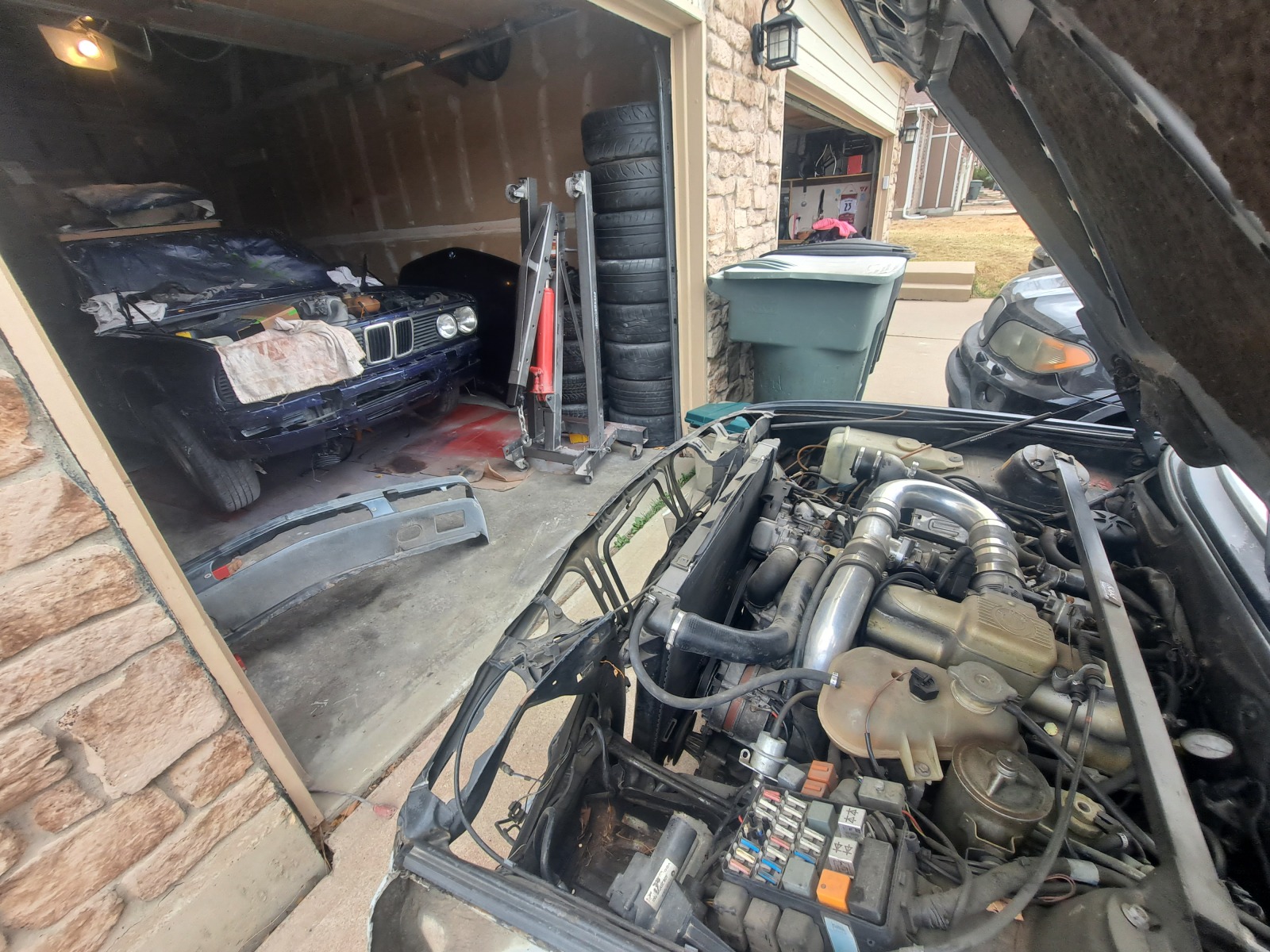
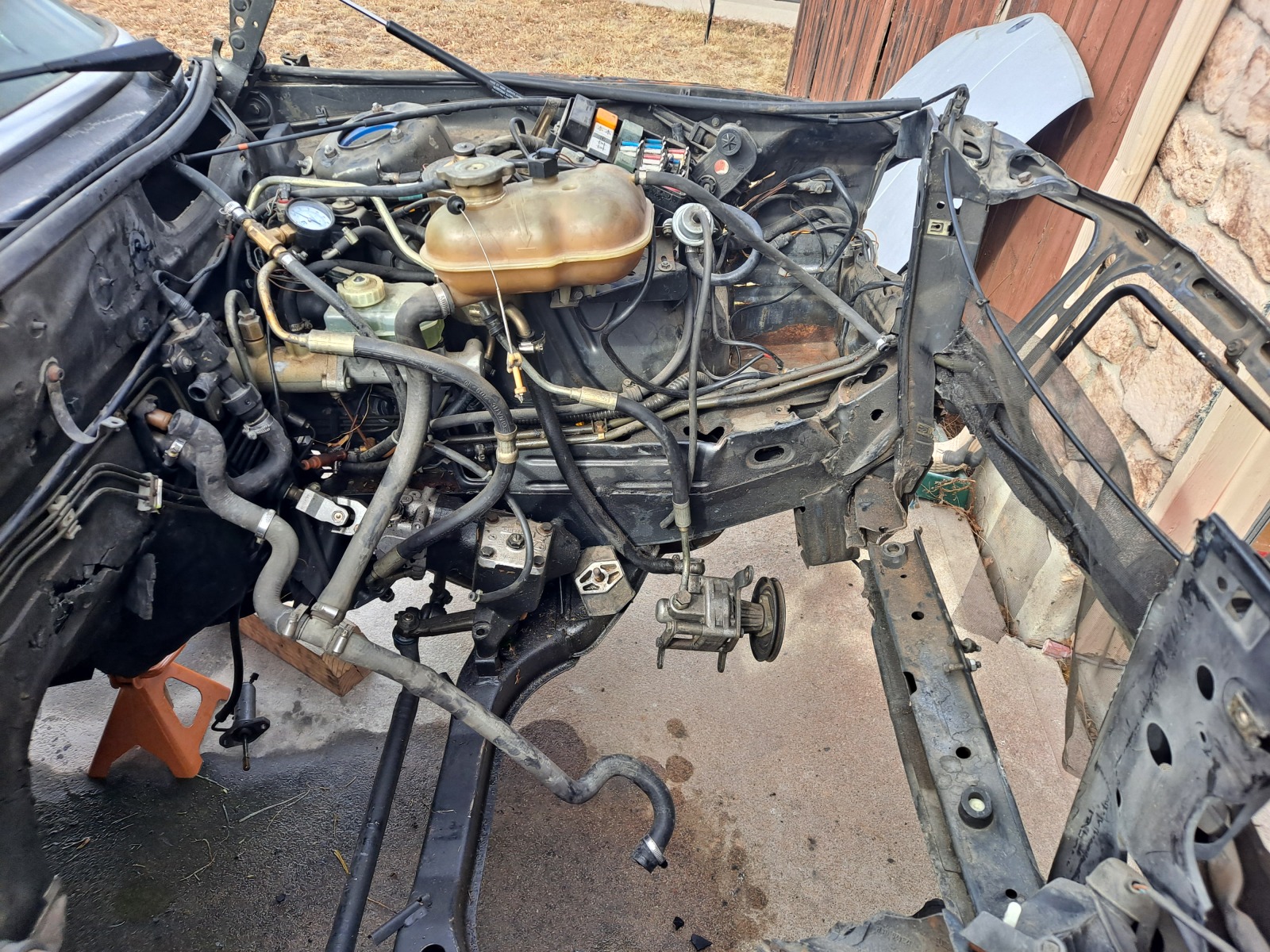
Here you see the 535is puleld out onto the driveway for me to start the work of disassembly and engine pull. I decided I could try to pull it on the driveway slope and I thought it might be flat enough for the engine hoist to not want to roll or tip (fortunately it was!).

Image

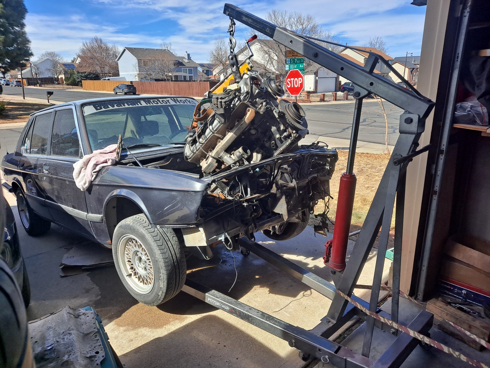
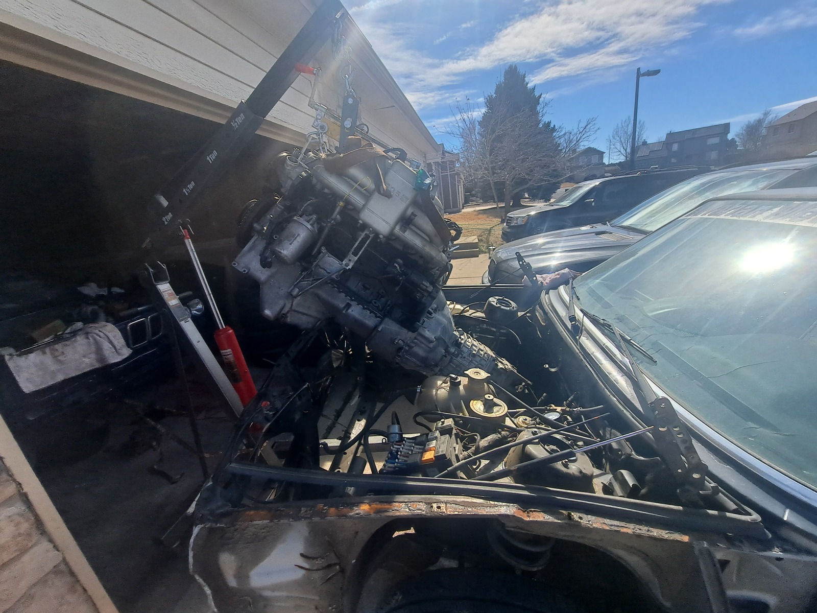
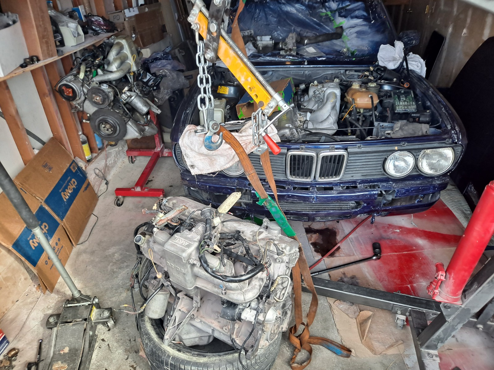
It took me a number of hours to disassemble and get everything ready, but I started the engine pull on Friday and decided without the full nose that I could pull it with the trans all together. Here's after I got it started coming out. I suspect the timing chain guide in this engine has some damage because there was a rattling sound when idling, though it ran fine and started right up.

Image

Image

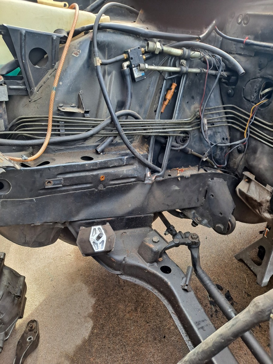
The frame damage, as I suspected it isn't great. So this was another reason why I didn't think that things could be repaired with just a nose/core radiator support.

Image

Image

My thought was to check the front guides out and go from there. Having a good B35 on the stand with a good headgasket and such is not a bad thing in general... At some point I will chekc it out and see if I can figure out what the problem was.

So here's my mix and match of engines at the moment... but it did get some of my spare parts back together.

Image

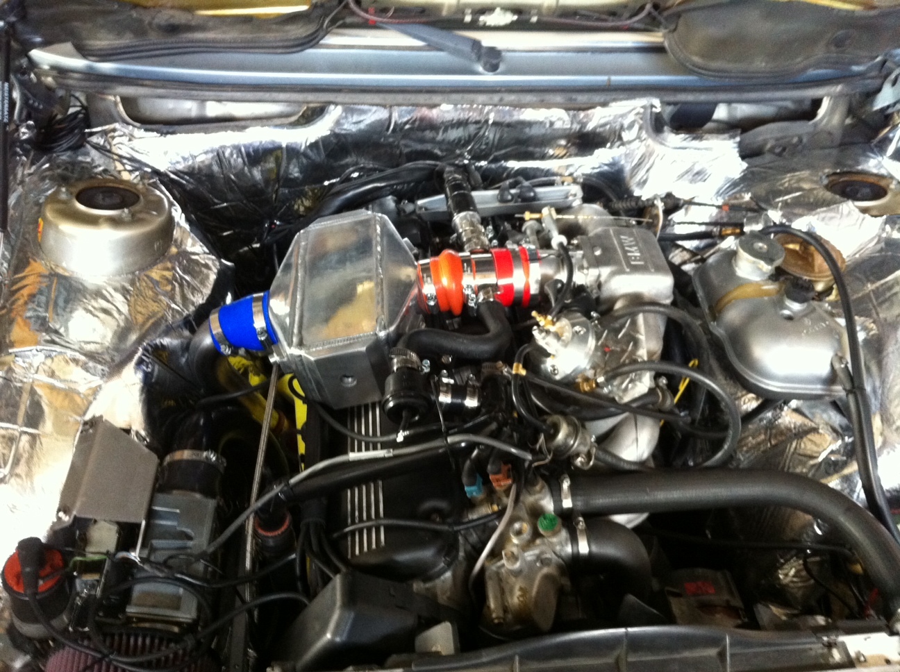
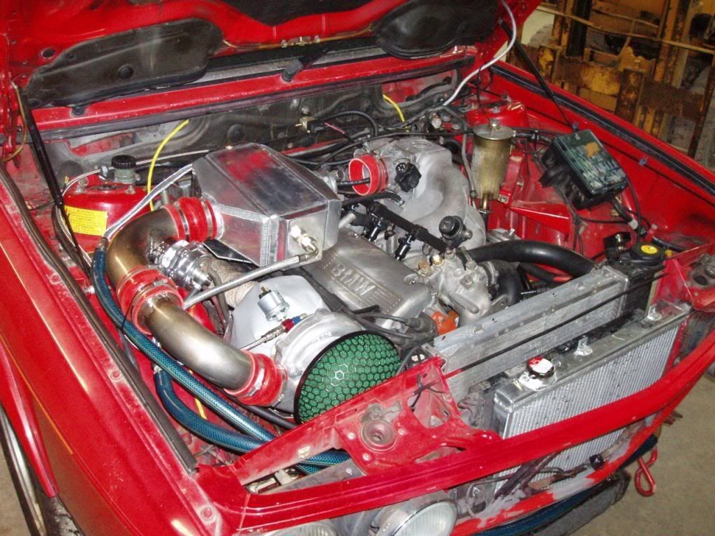
I am contemplating a liquid to air water intercooler. Here is a photo of another member on this forum. I found this intercooler but am looking for somethign similar but a little bigger. I have priced out some parts and thought it might be an interesting setup to try. The cooler I am looking at would allow a short intake tube like the TCD turbo setup and would be acore of something like 8x10"x3" with a little larger sized dimensions and woudl live above the engine.I'd probably need some sort of heat shield but am contemplating a setup with a pump down where the AC compressor lives and then a reservoir maybe close to the brake/clutch reservoir. Then fluid would run to a heat exchanger filling out the nose  the size of the AC condenser (approximately 16x20") with 3/4"/19mm hoses and a capacity of about 2 gallons of fluid. 

Image

I am not sure I want to spend the money for this setup (maybe $1000) versus another A/A intercooler for only $200. But it would be better suited to mountain runs at altitude and have better cooling for that situation. It may be worse at road course use, but I realize I haven't been doing much road course duty with the family at home. I am still thinking on it, but this would be a pretty nice sized configuration and would fit nicely behind the euro bumpers/airdam and be a 'different' layout than I have tried before. It should be more responsive with less air volume to fill by the turbo, and a decently clean package. With less flow restriction, the turbo won't work quite as hard so the setup should theoretically create slightly more power or more boost.
Flow I would imagine clockwise and this is the circuit I am thinking of with a very similar layout:
Image

Always curious to hear opinions on water/air intercooler. But it seems pretty well proven from what I have seen.


I did get the 535is back together with a spare trans, engine harness and ECU.. so it runs and I drove it back into the side yard. This means I have a movable parts car for when I am ready to swap the interior and other pieces onto the M535i. Next up, I will start reinstalling the clutch/flywheel and  removing pieces from the old B35 to put on the new B35 inside the M535i.

Re: Homebrew Turbo e28 (ex Callaway) - 2025 Update

Posted: Mar 23, 2026 12:12 PM
by tschultz
Ok another update. My last weeks have mainly been research and thinking about the intercooler setup and next steps.

As i said earlier, I got super lucky with this block being an early B35 because it has the correct mounting bosses. 1987 casting
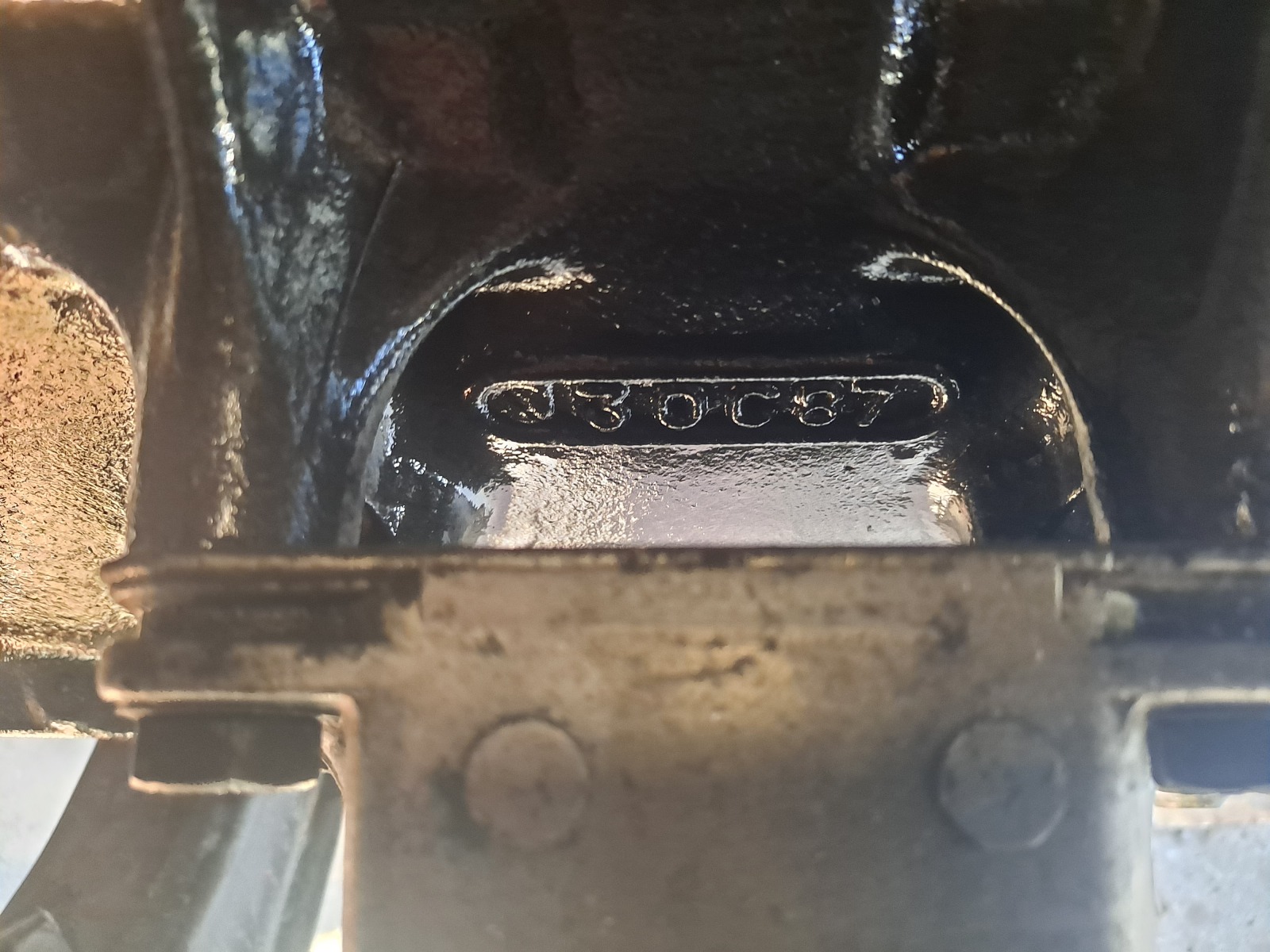
Image

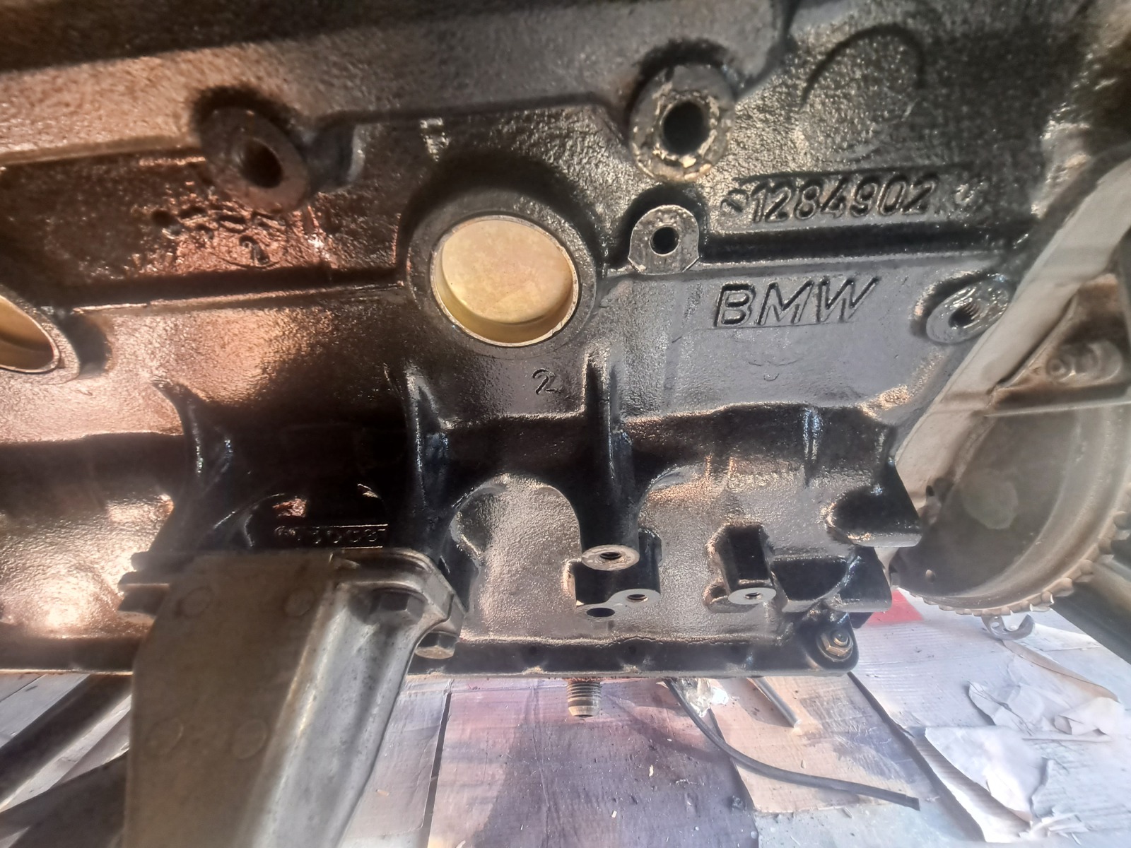
Mounting positions shown, with 533i/633 mounting arm and oil drain position (-12 AN) of oil pan.
Image

Not so much progress on the car visually, but it included reinstalling the engine mount, oil pan, turbo, turbo manifold and ARP head studs. I did a valve adjustment and think I will use the B35 valve cover (the B34 one has a nice grounding stud on the valve cover for my m1.1 harness, but i can make do without).

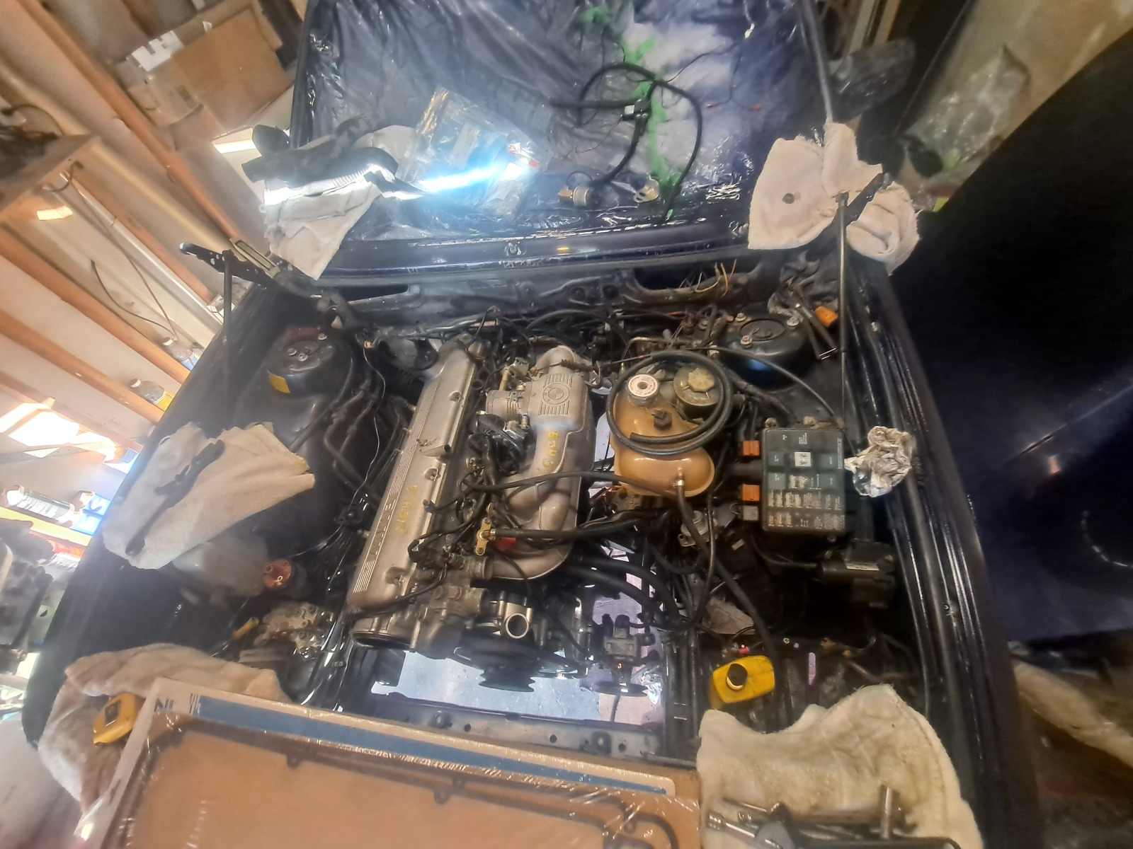
Engine installed with motor mount but needing many things hooked back together and installed. May put the FPR back in the OEM location, but I brought it over from the last setup, being remote mounted for IC piping clearance.
Image

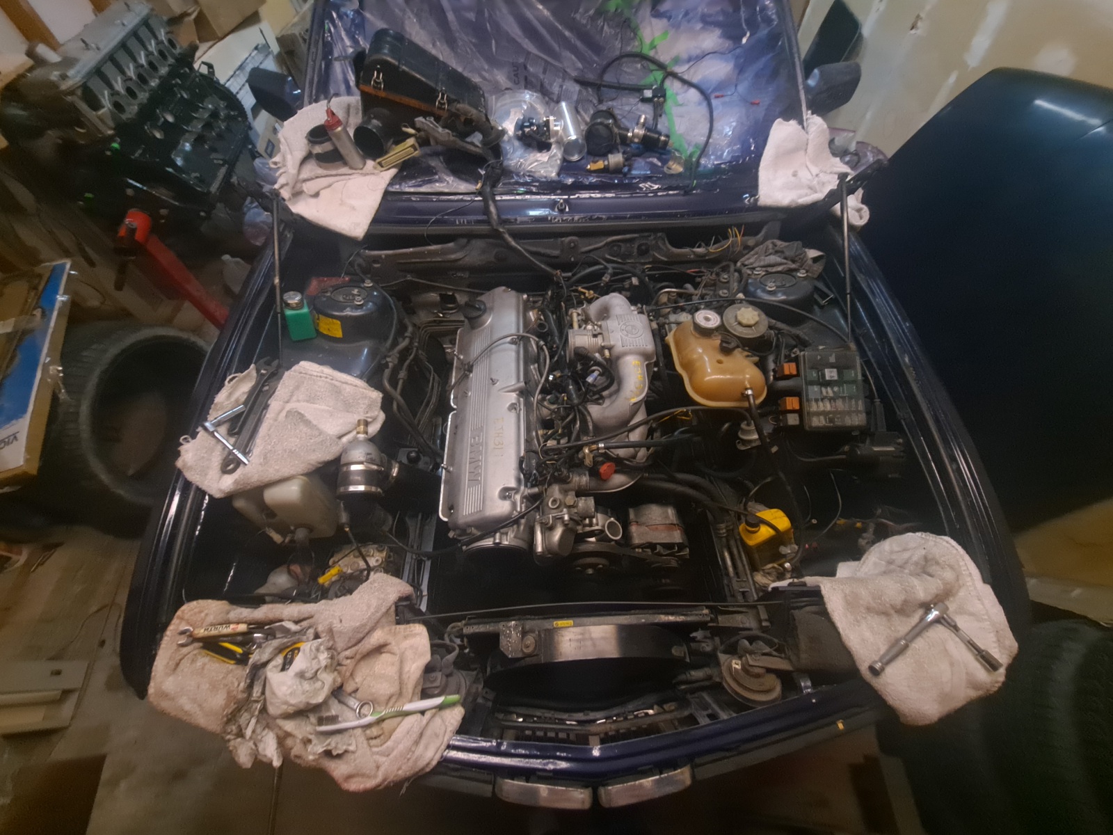
Manifold, turbo, oil pan, starter, alternator and pulley back on. Visually positioned with airbox/turbo inlet. Scoping out what space there is for components with or without AC.... AC not totally critical to me.
Image


I thought about what upgrades I might want to try now that I have the opportunity to keep AC or cut out different areas for a FMIC and different pipe routing. Overall, I was sort of thinking, what about the option for a water to air intercooler, wasted spark, or other mods? What would be the benefit or drawback? With this frame of mind, I thought LJ had a point that I could reimagine options, as I hadn't really considered waiter to air intercooling before due to complexity and weight.

As I researched it further, I saw a big appeal in reduced turbo lag-- some of this being because I am at 5000ft elevation and have lower response because of the ~18% less dense air. This gets exacerbated at higher elevations in the mountains as well. And one of the huge benefits of the W/A setup is that it can reduce inlet pressure drop and inlet intake tract volume on the M30. By my calculations, it should be reduced by 1/3 in volume to fill post turbo in the piping and 1-3psi less outlet pressure being forced upon the turbo.

Note that I measure boost pressure into the engine, not at the turbo outlet like some. This gives me a reading of true engine boost, but also means the turbo itself has previously had to work harder above that pressure to get flow through all the bends, piping and IC unit. So generally it means MORE HEAT coming out of the compressor to use an A/A vs the W/A. As I researched further, the W/A intercooler is generally more consistent in temperatures, say within 5F of ambient when cruising and steady state with normal cruise loads, and 15-20F above ambient at all times if the system is sized appropriately. An A/A I could get down to 10F quickly, but during a more boost, temperatures always creeped and had a larger variation after just a single run as things heated or cooled or speeds changed.

Additionally, in W2A you can select a different pump and hose size to flow more and achieve better cooling, or you can fit a slightly smaller core and heat exchanger and exceed cooling capacity of an A/A setup. Or you could do both! Specifically for low speeds and mountain runs, this sounded beneficial and interesting to try.
When i looked for a replacement intercooler of my last setup, price was about $200... but in new parts I can play with a few things and have some fun in setting up a unique system for not much more($750 all in?). 

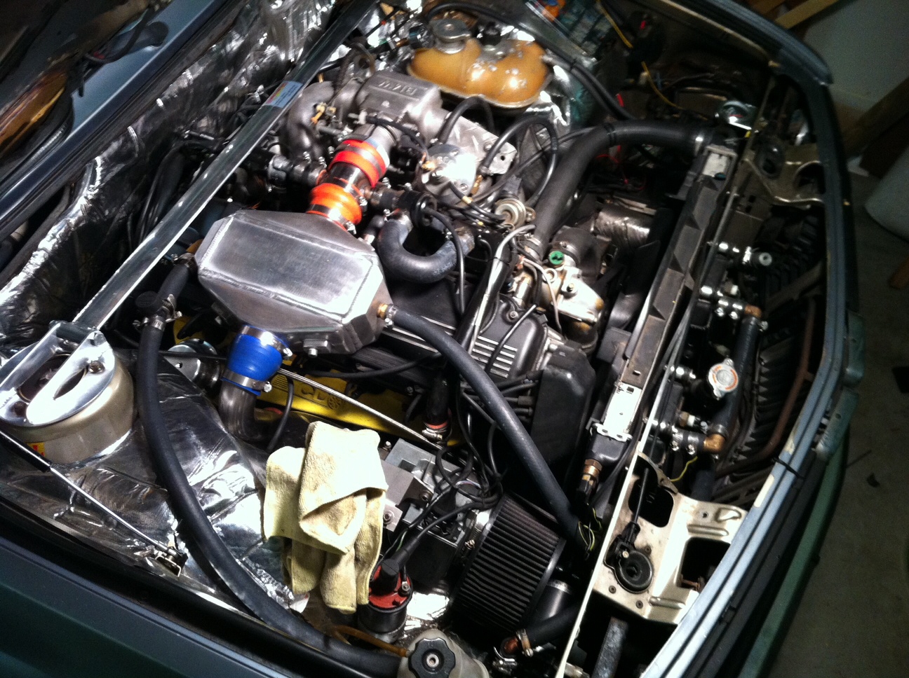
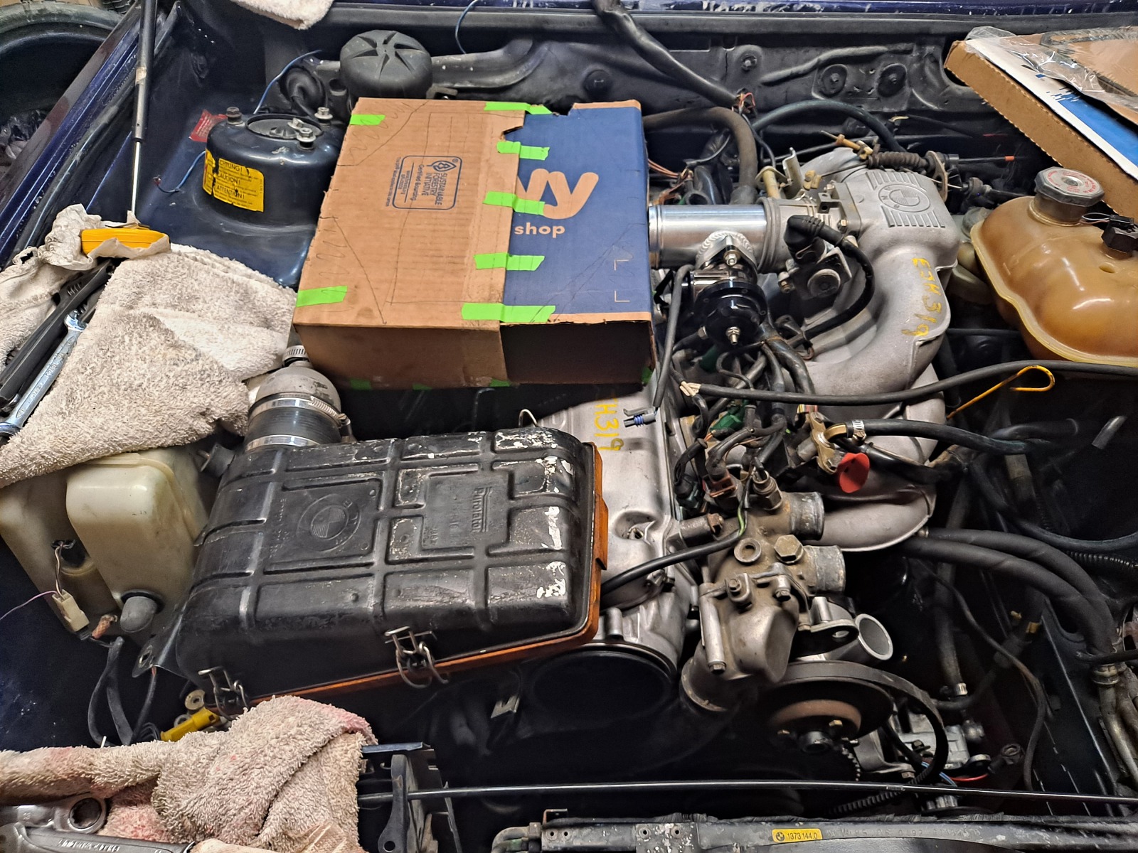
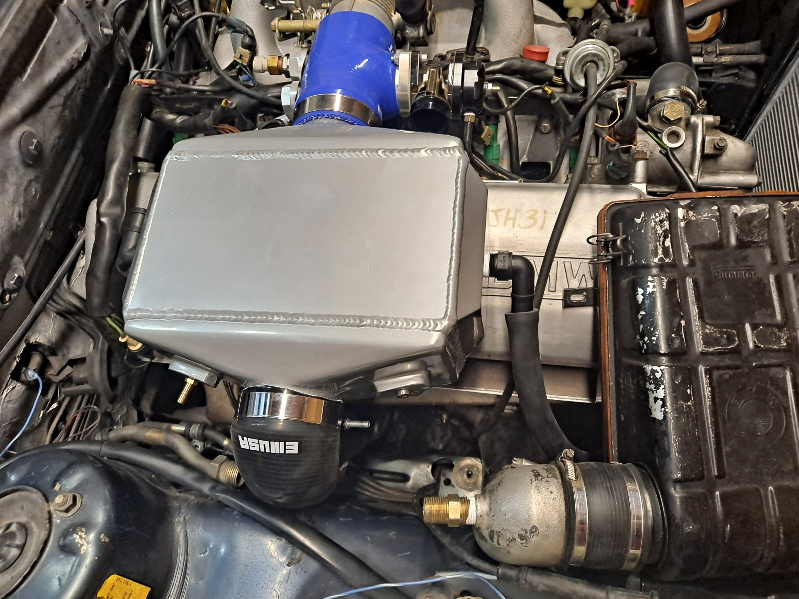
As I shared in the last post, a generic intercooler core can be used. I found one slightly bigger that I think will just barely fit, so I mocked it up with cardboard. You can see it has an L shaped path, but the shortest possible route to the intake--up and over the engine. The turbo outlet is vertical almost, and then with a single 90 degree bend and larger 3" coupler the flow can slow down a bit, hit a big core, spend a little time cooling off and then have a straight shot into the intake. Add idle air port and correct BOV after and all will actually barely fit! Here is the cardboard mock up:
Image

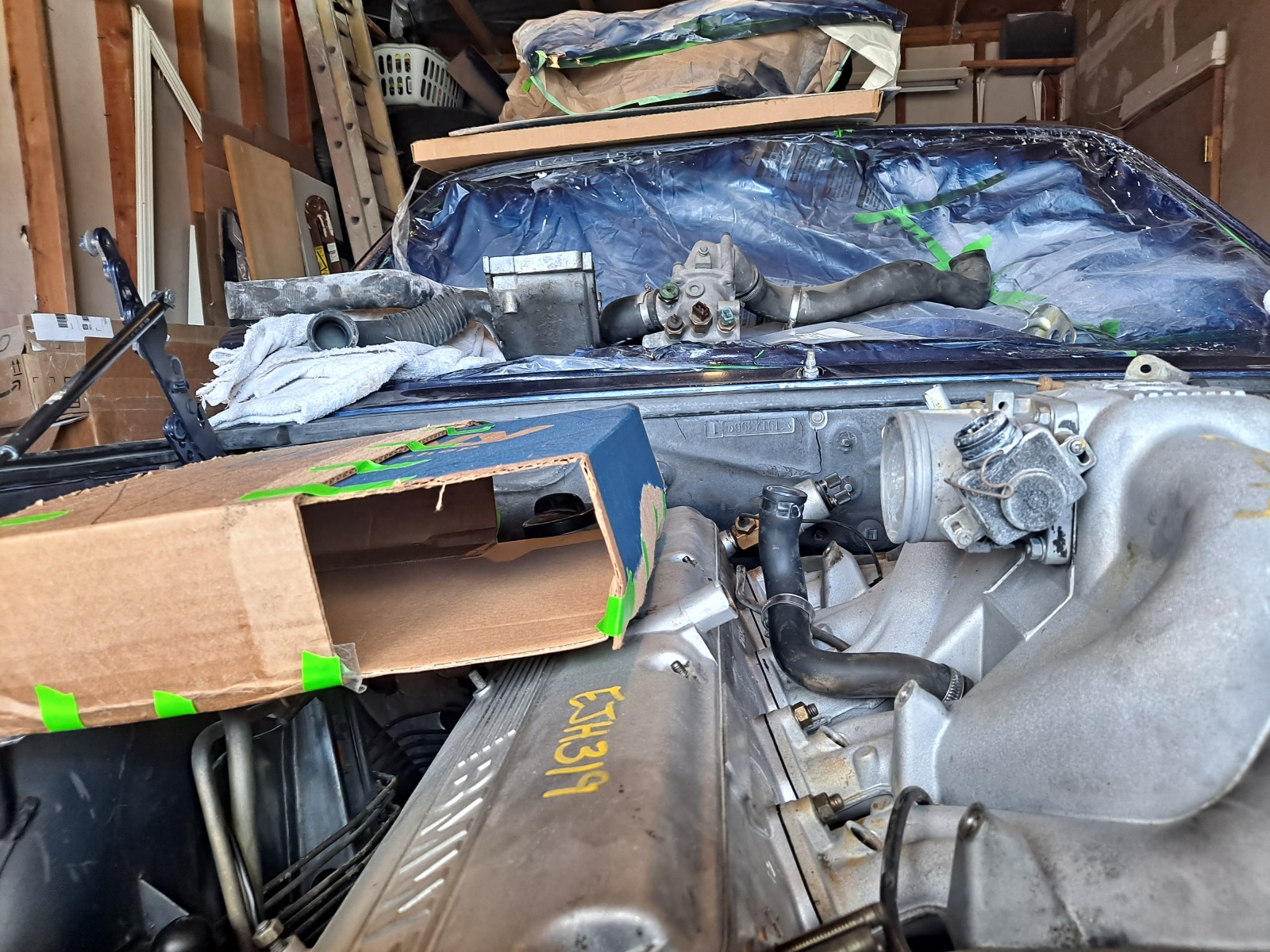
Top mounted above the valve cover is warm, but not as close to the exhaust manifold as what TCD uses, so maybe it will absorb similar or less heat. From my research, this IC core is about 20% bigger than the TCD intercooler (which itself previously cost $650 through Todd)).
It might just barely fit under the hood! 
Image

So i measured the AC condenser and see this as the prime spot for a W2A heat exchanger. I am looking at the biggest I can fit in this space, 22"x16"x2". Apparently this is usually the limiting item in a W2A setup. But the placement I am looking at will allow the use of the stock oil cooler as well, which means oil cooling capacity I didn't have before, without heating up the radiator. And for most daily use, the heat exchanger will be circulating water less than 100F, so it will actually not affect engine coolant cooling capacity. But when the oil does heat up there will be an extra capacity/volume from the oil cooler loop (over 7quarts), and the cooled oil will feed directly to the turbo identically to the old setup.

It will be a tight fit to plumb the water lines, but from what I see, flexible lines and pump placement will be possible. The biggest worry is the inlet to the heat exchanger just because there isn't a lot of room to snake a 3/4" (1.1" Outer diameter) hose past the headlights and into the nose.. but I will find a way.
One bonus to this is that I probably wouldn't need an e-fan. When at  low speeds and idling, the Mechanical fan will pull some air across the core and cool a bit in traffic....

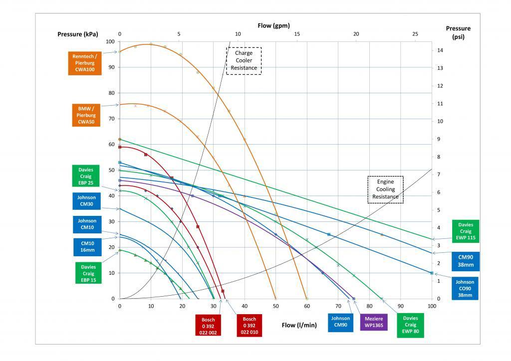
The outlet should go directly to the main pump which is an important component. I was originally looking at the Bosch 010 or a modified version which seemed sufficient until I stumbled on this chart. Not that there is a cooler resistance system line, so you can tell approximately where the pump may run based on a circulating system, all dependent on head (system losses/pressure). 
The system isn't my system, but it might be close and you can definitely see the general trend and impact of increased system pressure as you upsize the pump.
Image

I settled on a used Pierburg CWA50 which was affordable used and has a good reputation for reliability (used in german OEM's). I bought one used for less than $100. 
In this example, 27.5l/min (7.25gpm) vs the BOSCH 010 of 22l/min(5.8gpm) was the difference (about 20% increase, maybe moreso if my system pressure is lower). If my system pressure is lower (it should be because of no elbow fittings and single pass heat exchanger, decent IC with low restriction), I get more flow and better cooling. The big benefit being that this pump can be PWM speed controlled, which I am thinking of trying and uses a low 6A current even at max draw. I can also shut off the pump and still have cooling affect, or run at a low amperage to not overstress the electrical system. This was the main reason I avoided the CWA100 (~8.5GPM) which could run at 10+A, and the price of it was no cheaper than $260 that I could find. Most of these beefier pumps are $200 or more. Physically they are identical, so I could upsize in the future if I really decided it might help.
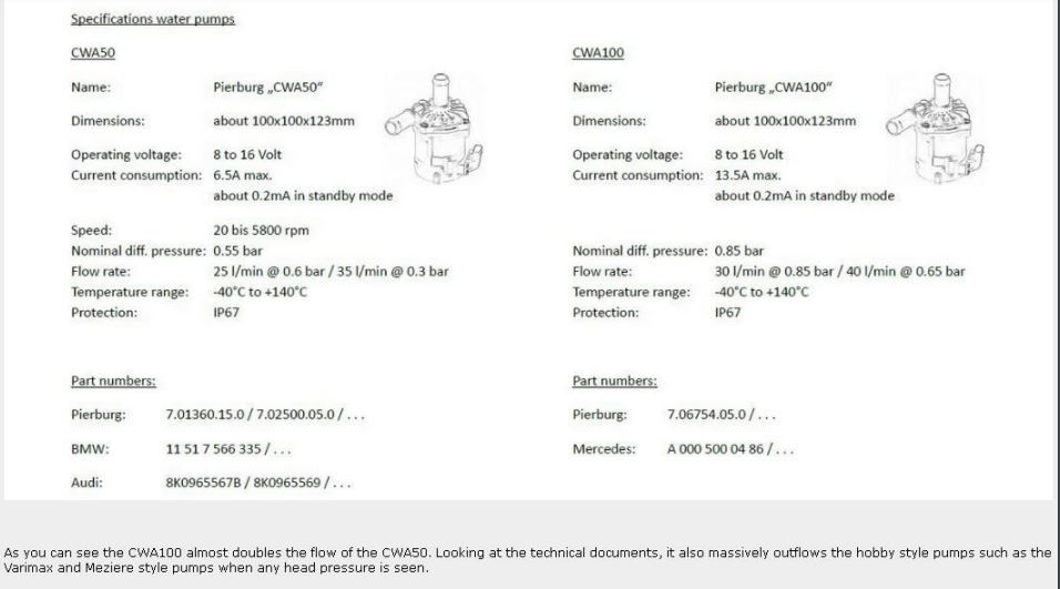
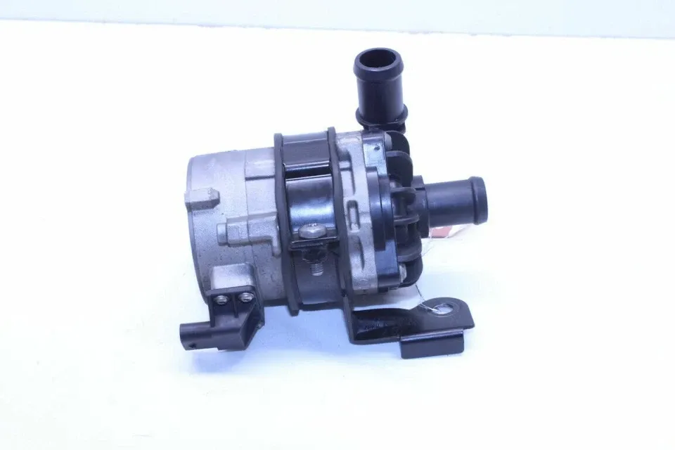
Image

Image
After removing the AC, the pump will live down low in the system close to where the AC compressor usually would be mounted. But it will be on the frame of the car, not hanging off the engine! So the wat will loop a route behind the fog light and into the pump and then shoot up vertically right into the intercooler with the coolest water temps possible 2 feet up and then through the core along the length of the engine toward the passenger and oil fill cap.

As I mapped it out, I wanted to get a water reservoir. I stumped upon this E36 expansion tank and liked it because of a split vertical divider. So flow can go in vertically, air can settle out as it flows up and over the divider and then drops back down while being sucked out the other opening in a closed loop system. The inlet and outlet ports looked close to the 3/4"/19mm I was hoping for, and the price was low enough as well at ~$30.
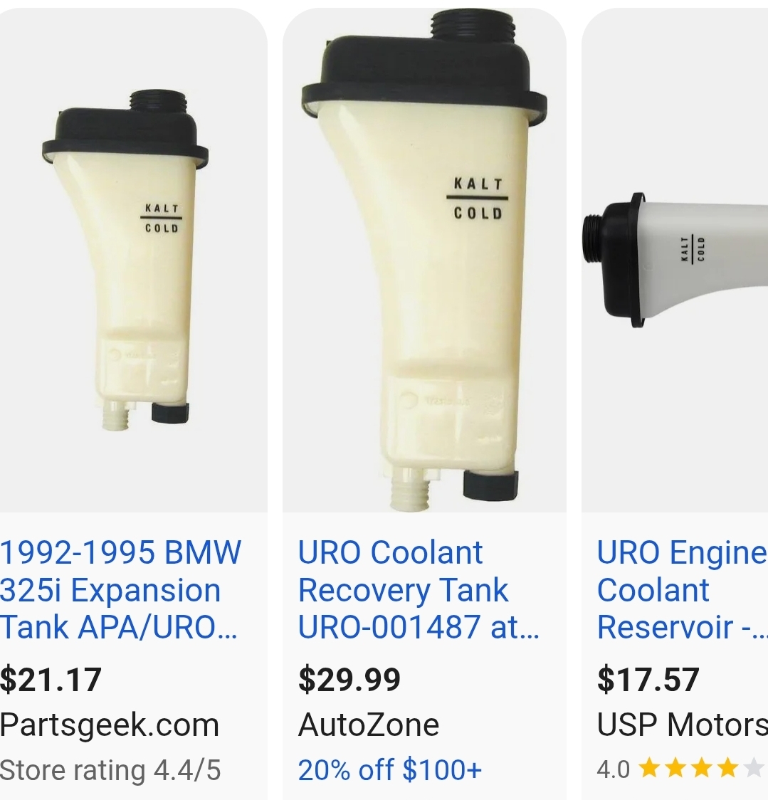
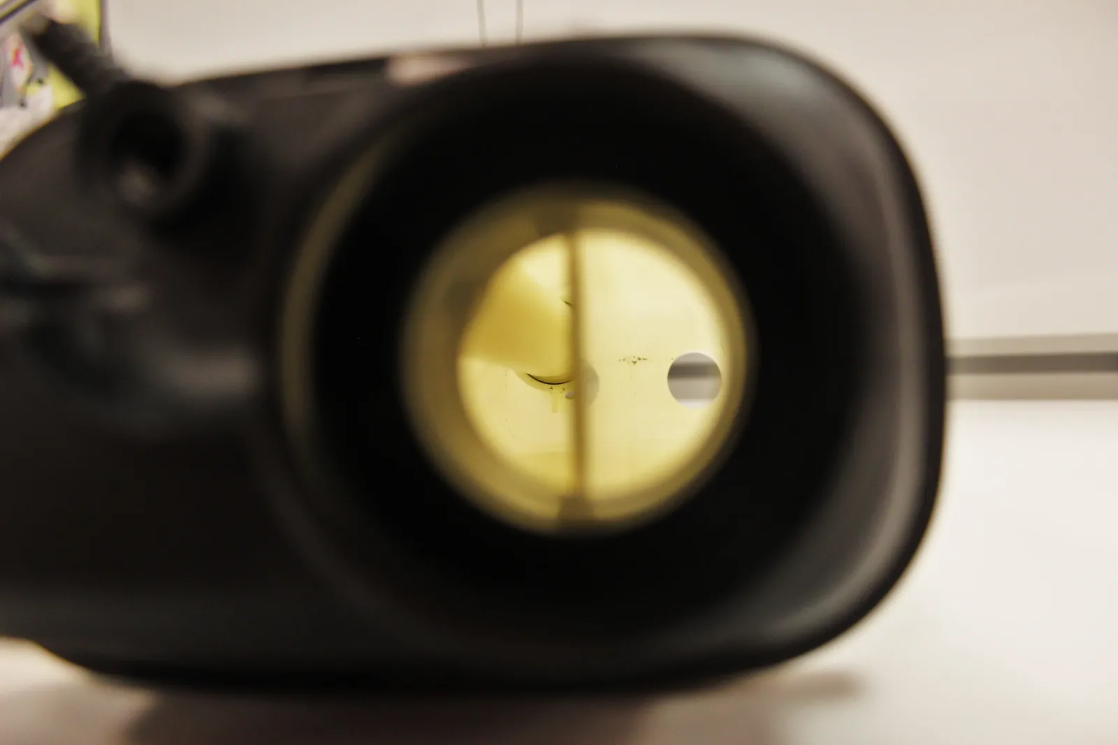
Image

Image

The system I think usually gets coolant overflow through the top port from the radiator and this side of the divider in E36's establishes the height for the level sensor. I will use it differently but think it will work for what I need. This will catch the air bubbles and allow splashing around all while still being the collection for air bubbles. I think the system will have to be mostly filled to the brim, just above the the height of the divider for the system to work properly and collect air from elsewhere in the loop. It also has a bleeder screw and a small access bleed hose if i really need to top up the system somehow.

More details and photos here, but I saved their images: https://www.mishimoto.eu/media/magefan_ ... rnal-3.jpg

It has 3 open areas, and the port normally for the level sender has a small split and tube above it. This will definitely do what I need to allow air to collect because of the passageways and internal path for air to escape via the tube. I think water in the main opening will fill that side, and then any air bubbles can collect in the other 2 chambers, but there is a larger volume and lower opening for draining of the fluid back into the bottom return.
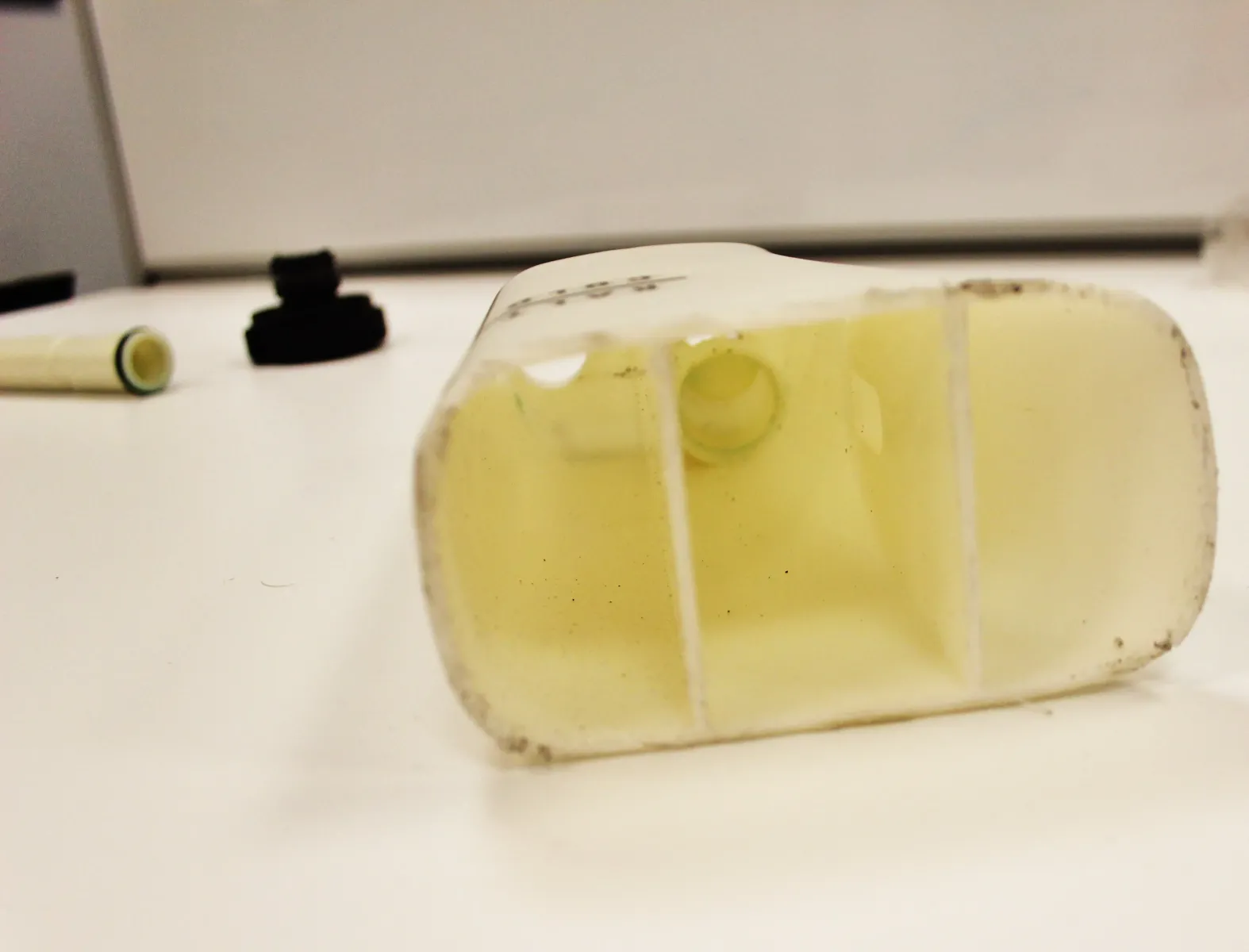
Image

The outlet will use gravity and pull from the lowest point (typically the sender side), minimizing air bubbles (i hope).
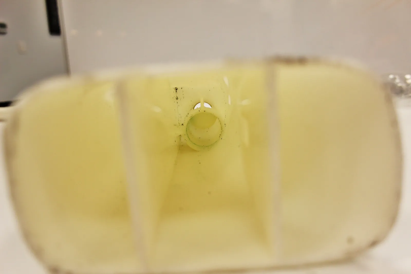
Image

The tube and cap inside is interesting and maybe would also be a small air pocket if totally filled to the brim before priming the system.
https://drive4corners.com/wp-content/us ... nal-6.webp
https://drive4corners.com/wp-content/us ... al-14.webp

Capacity would have been nice to be bigger, but the important part was the width (~3") which seemed like it could fit near my brake master and hydroboost bomb, along with the 2 large ports. It is also designed for coolant and will definitely hold ~4-5psi of the water loop. But the placement will be on the cold side of the engine and the plastic tank will mean the water can remain insulated from engine bay temperatures better than an aluminum tank. I can maybe run the bleed line directly to the heat exchanger because it is open to the tank insides and not just the vent cap. Inlet and outlet will be vertical (hopefully to burp all bubbles).
This solution was actually kind of exciting to find!

I ordered one and also the intercooler.

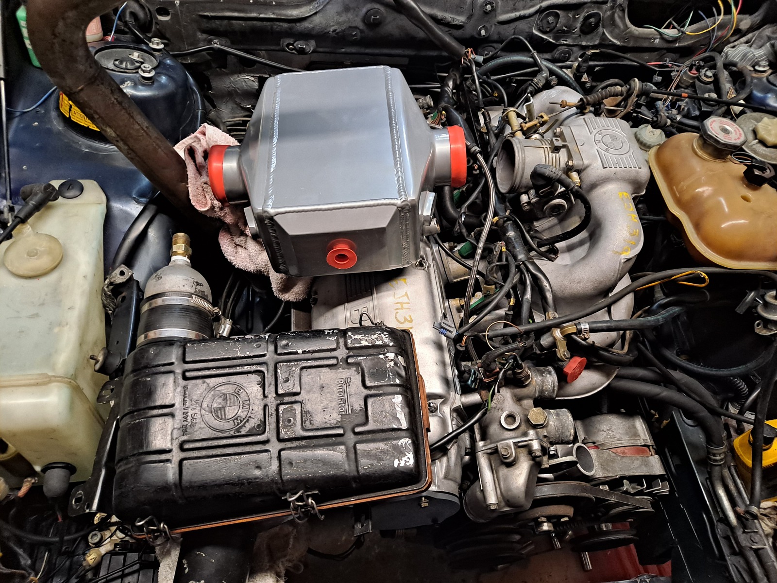
It arrived and I placed the IC on the engine. I think with some adhesive/rubber on the valve cover and then a mounting bracket or 2 to the B35 valve cover, it should work! It is a tight squeeze to the hood, as expected -  I hope it all fits!!! Eventually maybe some insulating heat reflective foil of some kind.
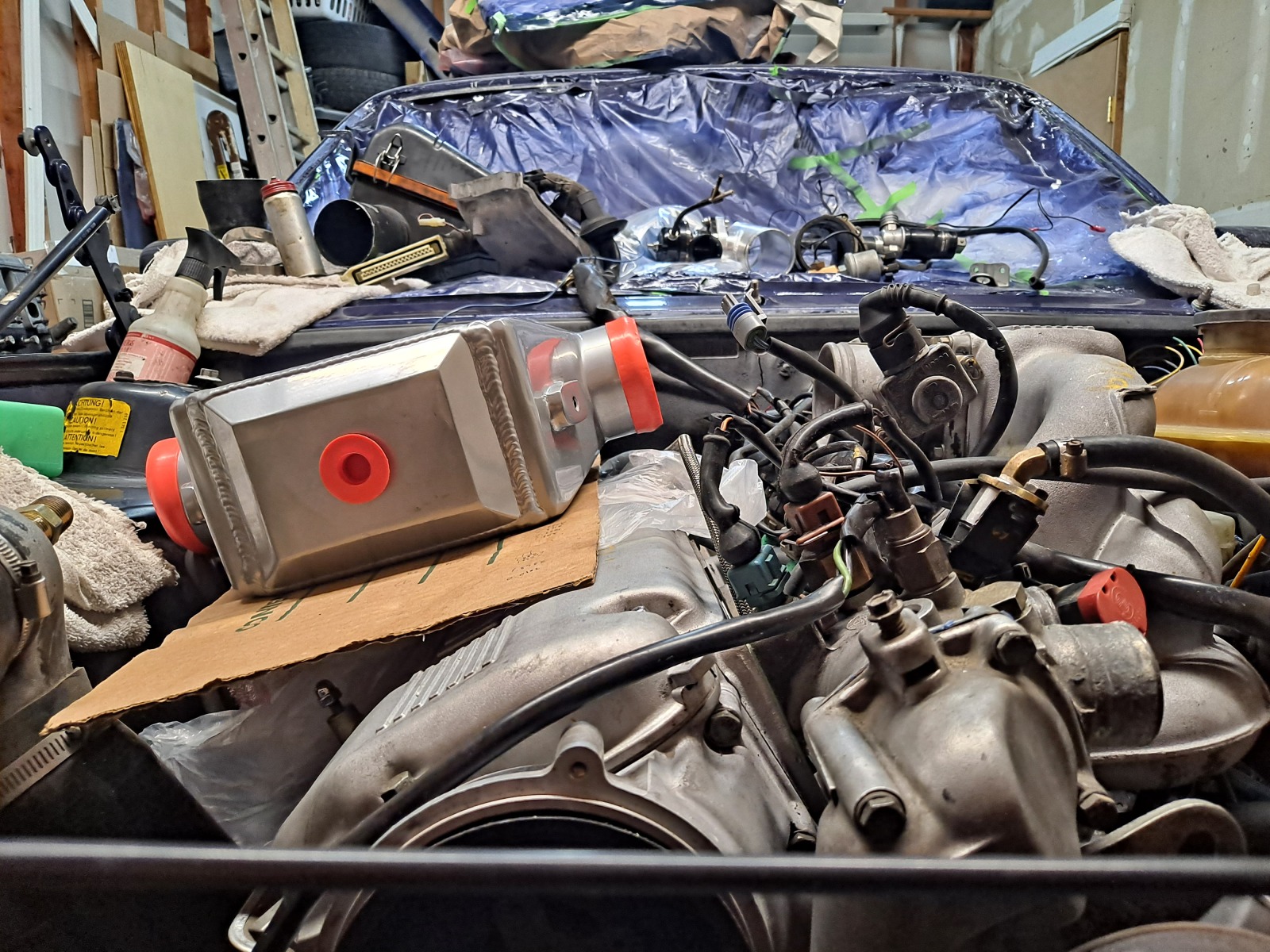
Image

Tank location and approximate intercooler position, I can find a way to mount both securely. Should also fit with the strut bar installed.:
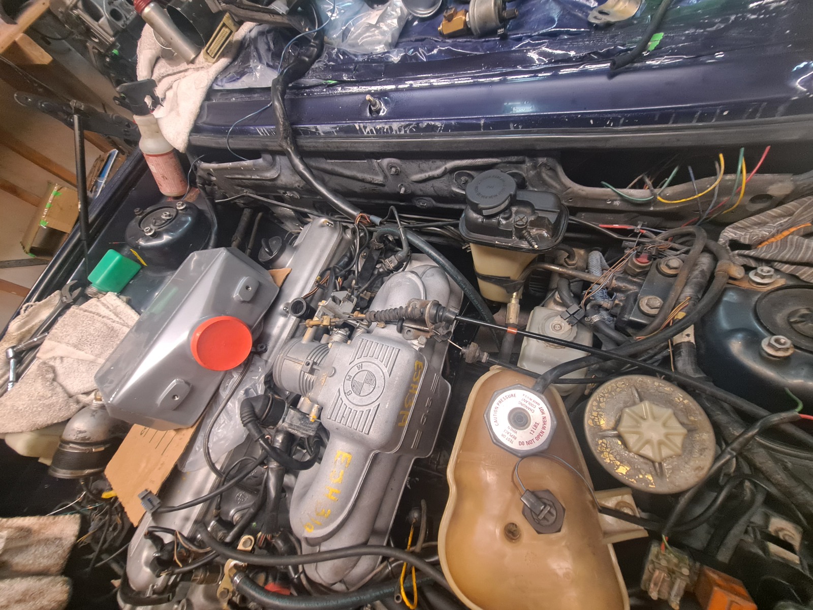
Image

Lastly, I am contemplating a PWM controller to run the pump with a variable control from the cabin. Also as an on/off switch. I am not sure that it really needs to be shut off or programmed and controlled by the MS2 but I was also thinking about this, on above 165F coolant temps OR MAT above 80 F. Maybe try it with both, because a manual control of the pump for filling and bleeding after maintenance would be handy, especially if the laptop wasn't in the car and I wanted to shut the pump off because the system developed a small leak while being out and about...

With all of this, I am also contemplating wasted spark as I alluded to in a previous post. I have the coils now and I think I can program them and solder the chips TC4427 onto my board for 3 spark outputs. I just need some small wiring and soldering changes. I have room on the proto area and would test it with jimstim. I think this would give a better idle and slightly more reliable spark.
Just for reference for my self with my spare Ms2 unit, here are the TC4427 units and the associated wiring on an incomplete ms2 v3.0 board.
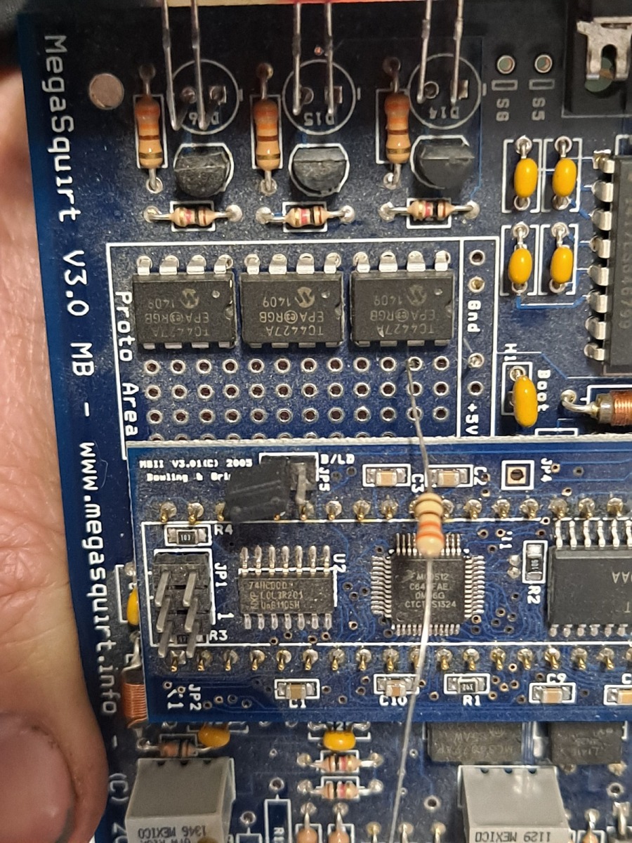
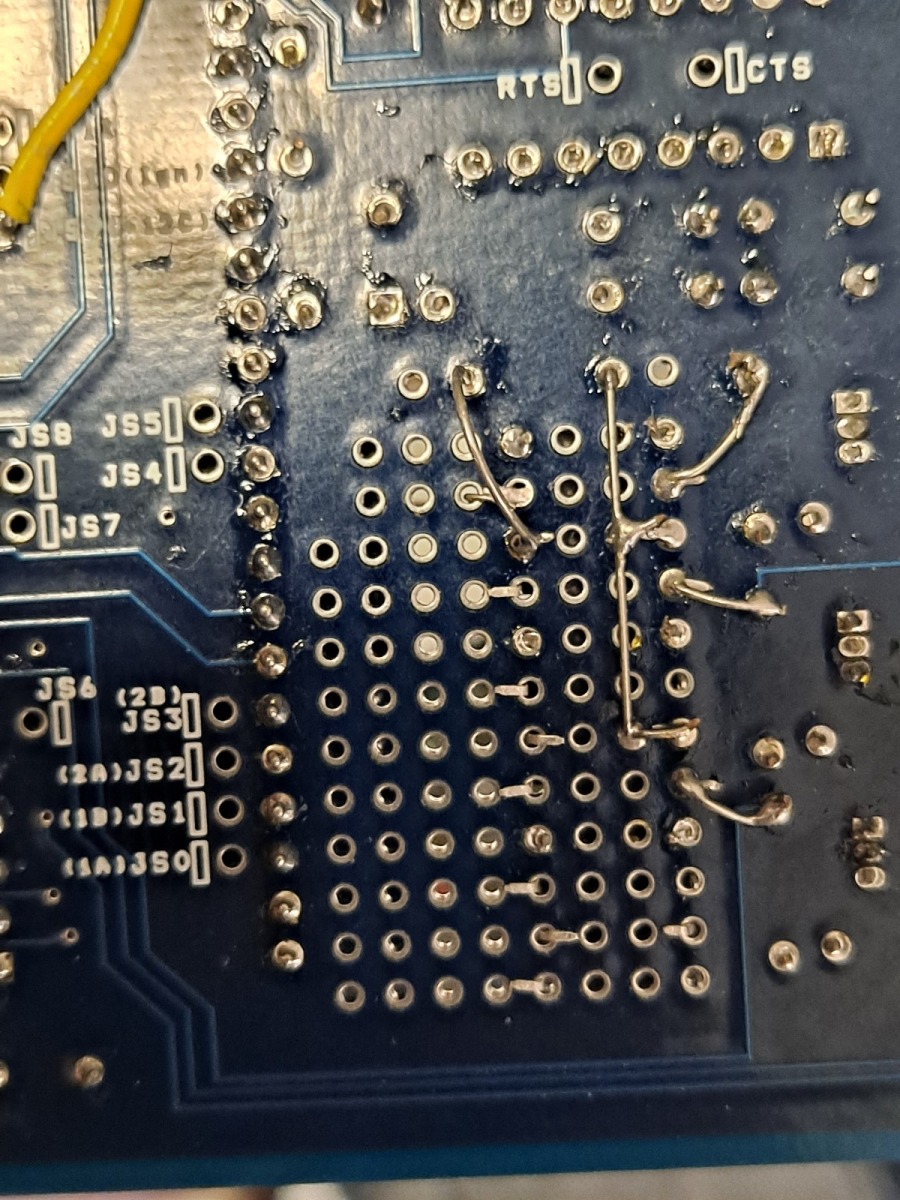
Image

Image

I would mount the coils down near the ABS module (under my airbox) with a custom bracket solution I build and then would need to simply wire up the outputs and power to the 6 coils. I think the stock spark plug wires would reach, and all would be somewhat hidden under the airbox.
Basically mounted back to back but I need to figure this out further. I'd just need a cam/distributor cover plate.


Maybe a last photo for motivation, but this should be close to how the car will end up looking, some image i found on the web, I don't know if it is RoyalBlue or some other color:
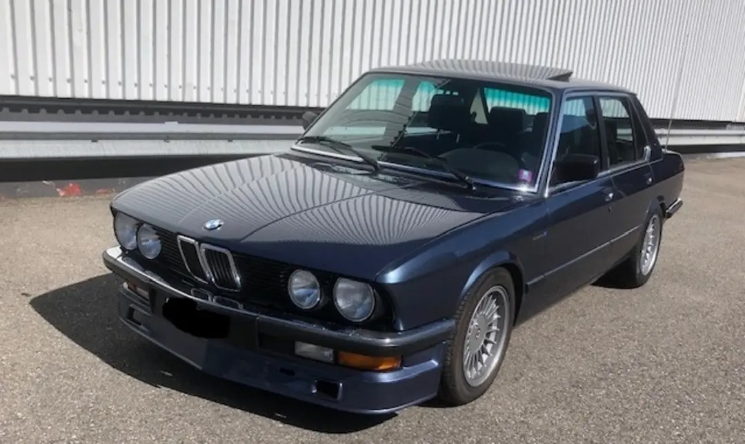
Image

Oh and an AI generated image, definitely has some limitations, but I thought it looked decent!
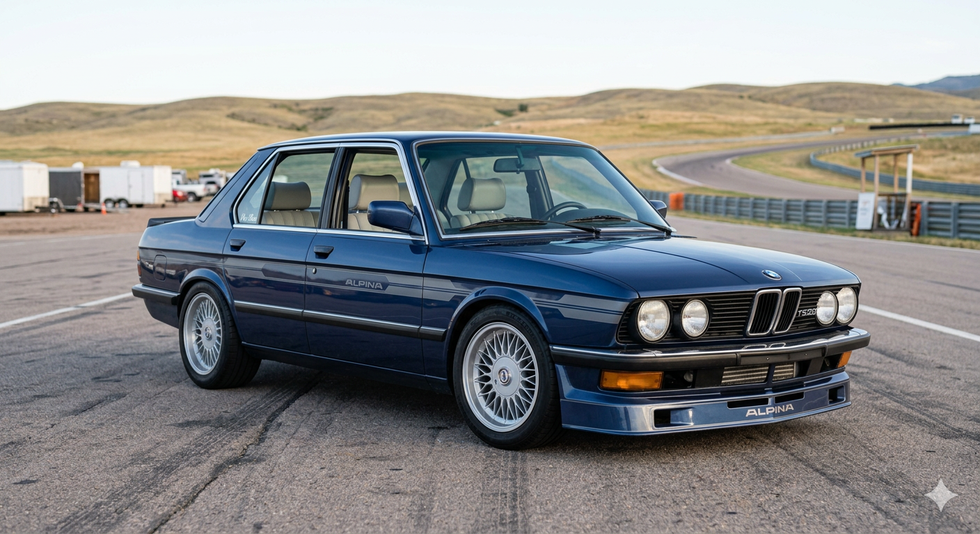
Image

I have lots of work to do still, but little by little I will keep moving on it! Next up, likely clutch and maybe transmission and ordering of more parts!

Re: Homebrew Turbo e28 - 2026+ Update W2A

Posted: Mar 30, 2026 6:07 PM
by tschultz
So a week later and I have a bit of progress. I was thinking more about this and trying to piece together the benefit of this system and imagining if it would all fit or what improvement it may give in my system.

The intercooler core is approximately 11"x4.5"x 6" deep and an internal volume of about 281 in3 (~50 sqin surface area). I received it and did a mock up of placement. It will be a tight fit but I think it will work! I ordered a few couplers and fittings and mapped out the layout of liquid and piping.

Image


The tcd 535i core is a wider setup that I found dimensions of the core to be 18"x3.5" x 3.5" deep (~64 sqin surface area, 221 in3 volume). The TCD is not easily found nowadays, but with the shape and frontal area, it would be quite efficient. What I am unsure of is if it picks up a lot of heat by being so close to the turbo manifold (right next to it). But when i found the dimensions, I thought it would be interesting to compare against with the core I selected.

Not a lot of information on W2A setups, but from my estimations, the wider TCD core would be more 'efficient' in general (wider area of hot turbo air (240F according to matchbot) hitting the face. Bigger delta T means more cooling affect. But the deeper core that I bought is longer, meaning there is a bit more time for the air to be cooled and more volume of water to be heated. With the extra 30% volume in the larger core and slower air speeds, I would expect the cooling affect will be similar. So that just means maybe i can expect some similar performance to others with the TCD kit, maybe better if I have a better pump and volume of water through the system than the lines TCD suggested.
With the W2A vs A2A intercooler, there will be less pressure drop through the core and less lag since the IC piping volume is less. So I am expecting the turbo outlet temp to be a bit lower since the turbo will be working a bit less hard at the same 180kpa boost pressures as the old setup. But I think there will also be less losses, both low rpm and high rpm. So it should be overall more responsive and quicker in and out of throttle transitions. This is important at higher elevations of 8000+ and above, and one of the key features I wanted to improve on. Accelerating out of turns was great, but a bit slow in the mountains when you have to wait for the turbo to spool.

I picked the heat exchanger and just hoped it would be able to fit in my setup! The heat exchanger is the main component that sheds the heat from the water after it is heated up inside the IC, so this is the reason why I picked the largest one I could practically fit. I figured bigger is better here and fit as large as possible while retaining the oil cooler from factory. If a fan is necessary, I could add one, but I think the mechanical fan will pull air through the radiator at low speeds. From some rudimentary calculations, the water temperature should be 90-110F maximum, even in heavy loads, so it actually won't really affect engine cooling from normal.

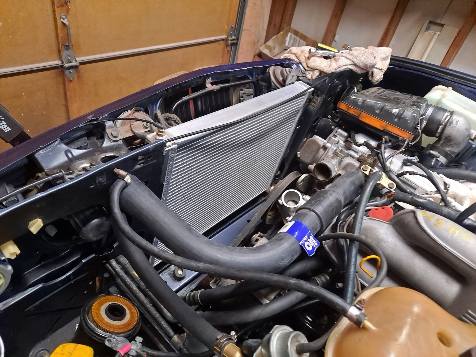
The IC is about 22x16x2" with the core slightly smaller and the fittings making it slightly longer. I cut off one end of the inlet fitting to shorten the entire length and allow it to fit in the nose of the car. It is about as big as I can get, and I had to adjust the oil cooler lines slightly for all to fit. Luckily, I found a way to make it work, though I had some very minor trimming. I added a hole into the radiator support for the hose ~1.2" to pass through near the hood latch.

You can see the 3/4" water hose coming in near the headlight boot/electrical cover before it turns 90 into the top corner.
Image

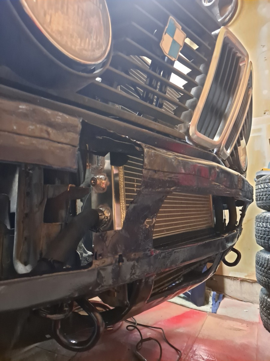
The outlet comes out the lower opposite corner and slopes downward to the pump. This whole lower section should be visible to the fresh outside air, though the oil cooler may be blocked a bit from the alpina airdam. It will still cool, expecially with the added oil capacity if the thermostat does open.
Image


As I understand, the pump changes how quickly fresh cool water can recirculate for the cooling affect. I believe the CWA50 was a good sized pump start with. I found the mounting spot a few days back-- It is living in front of the motor mount of the subframe and I just need to get it wired in to the external PWM/speed controller. I am planning to have it operate by mechanical fan (temperature switch on the radiator) or by selector switch in the cockpit (likely the AC Snowflake button :cool: ) on manual/override mode.
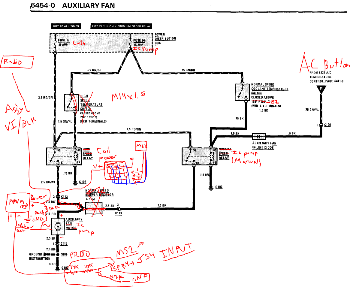
Here's what I am thinking of doing to make it work with factory relays and single signal wire to power the pump from the external pwm controller (wired into the radio or similar accessory/run position.

Image

It would be cool to use the input of the pump and log it inside megasquirt. So to do that, I will have to modify the circuit a little bit. I am thinking about this, as well as the wasted spark system. I probably won't modify this until I have the car running with the single coil, but it is within my plans. I may need a wire bundle out of the ms2 case to make all of this work because there are limited output pins available through the DB37 and main harness. So i can ground and bundle appropriately if I make my own connector and case output.

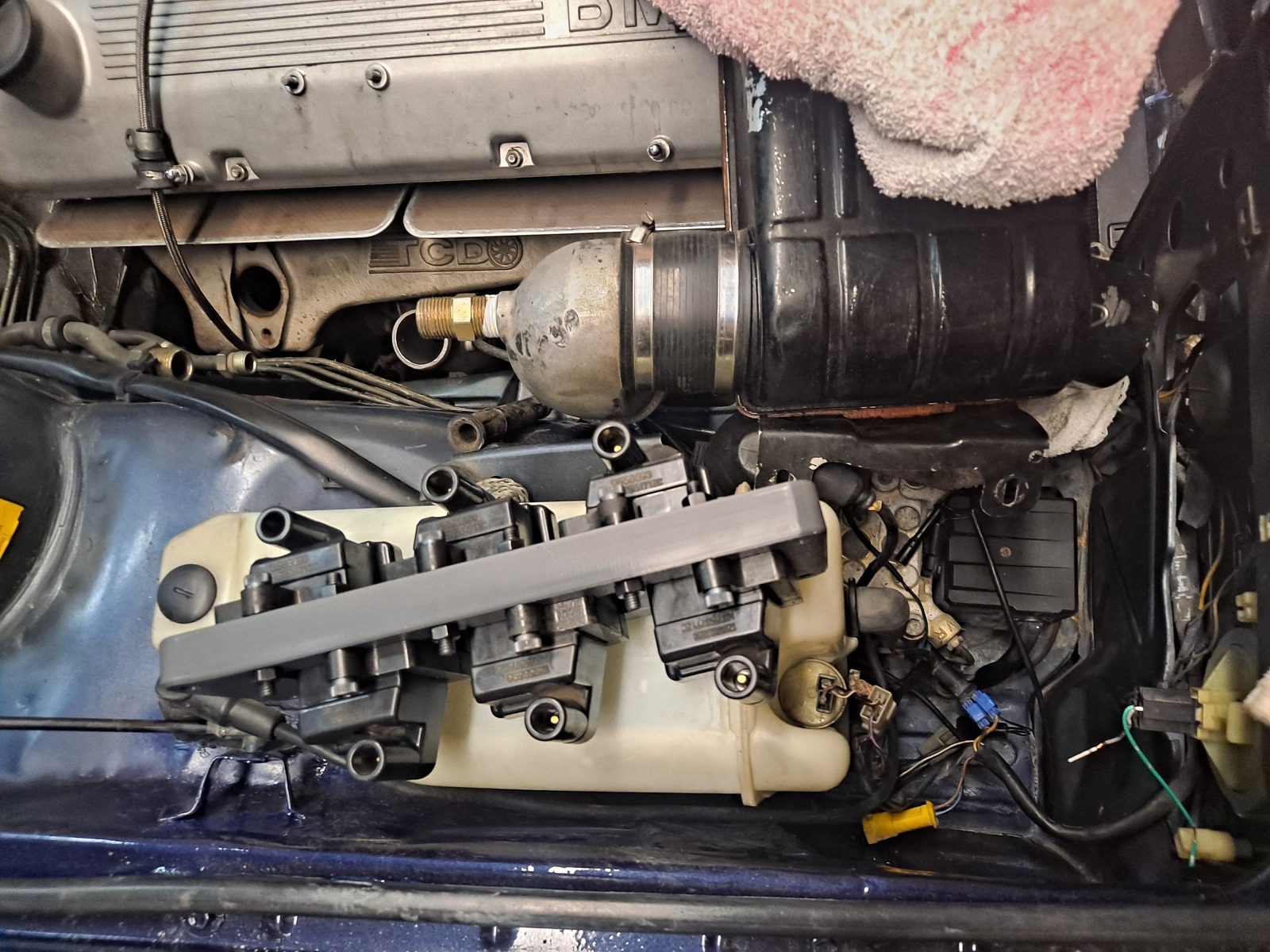
I 3d printed a small coil holder and mounted the coils in place. It will in fact fit down by the ABS module, which would be the final location I think.
Image


Last specifics, according to calculations at ~500-550 CFM flow, the engine will need to reject 115,000BTU/hr. With turbo inlet of 75 F ambient air, the turbo should be producing 240-250F compressed air. If I assume steady state here, an AI prompt with ~7gpm flow through the hoses size I have selected suggest IAT/MAT from 105-125F and water temperature of the intercooler of about 110F.

So that would be steady state of heavy use (14psi at 5000rpm continuous). I am hoping this will translate into about 15 F above ambient in most all driving situations except for heavy use on boost. The benefit being in short bursts that the temperature will return to basically ambient in very short period of time, even at lower speeds. It should be 'better' than a/a with more consistent IAT's, better response and acceleration due to this, but also cooler IAT's during a few hard accelerations. I am not sure it will be much better otherwise, but I wanted to try it and see. After the fact, hope the engine bay is a bit nicer looking too... basically stock looking except with a big square box on top of the valve cover :laugh:

A/A seems simpler and cheaper, but I will be curious to see what the W2A benefit really is. It should be better response and boost build. I definitively haven't gone too small in the core or heat exchanger size. I would guess a few HP since the less pressure drop and more consistent temps means lower intake temperatures through a run. Alternatively, I could bump up boost by another 2 psi and get 30 or 40hp more over the old A/A setup  and similar intake temps :lol:

Re: Homebrew Turbo e28 - 2026+ Update W2A

Posted: Apr 04, 2026 1:27 PM
by Nebraska_e28
Looking good!  This is gonna be a fun ride when done.

I'm unsure how much benefit there is to individual GM coil packs vs wasted spark or at what HP level this becomes relevant. I'd suspect for individual coils to perform, you would sequential injection, adjustable timing gear with trigger wheel. Oh, and monitoring of EGT temps as another data point to adjust maps. 

I really like the HE idea of larger being better. There was a build where someone ran dual HE up front with 745i mani. I never saw any data logs, but was always curious of IAT under sustained boost.  

With your IC placement, I think the challenge you will battle is heat soak due to placement above the mani & motor. A heat shield may be in your future. 😉 Since you have an ABS car, that limits placement in the front wheel well. If you end up considering a flipped intake setup, you could run your IC on the driver side or potentially in the front driver wheel well. Maybe. For a future project, I contemplated flipped mani & placing the HE in the lower wheel well after removing the battery tray. This essentially gets everything away from sources of internal heat. 

Just food for thought. 

You'll love royalblau! Is shows some very unique hues in the sun. 

Re: Homebrew Turbo e28 - 2026+ Update W2A

Posted: Apr 06, 2026 12:21 PM
by tschultz
Thanks LJ!

I don't expect more maximum power from the W2A over A2A for the same levels of engine boost or single pull performance. But it should be more consistent for IAT's in harder sustained use or climbing such as in the mountains. I read approximately 1% engine power per 10 F of intake temps...
The lower pressure drop through the intercooler and piping means less boost that the turbo is providing and less heat in the charged air-- estimates show it could be 20-30F lower compressor outlet temps just because of lower pressure drop in the IC piping. This could be maybe 10-15 ft-lbs, and the difference in building boost-- I am curious to see the difference in feel/response. I will be able to  compare this to datalogs I have of the old setup of single highway pulls.

Yes, I am looking up insulation methods and thinking about a heat shield if necessary. I have the heat shield near the spark plugs so the main heat is radiant heat and conduction from the valve cover area.

Here is Cupholder Turbo's setup, which is a similar but smaller core. It fit, though he didn't have datalogging to know IAT's. He also used 2 small heat exchangers and a small pump, though I don't know how well his setup worked.
Image

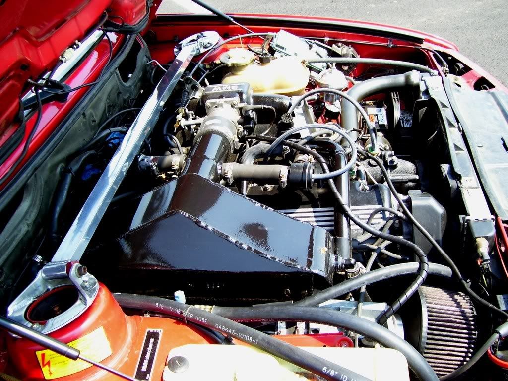
And another user here on the forum who did W2A, but with RHD and also a top mount turbo with AC: 
Image

Lastly, TCD intercooler position... It may get more heat from the manifold but a bit less heat from the valve cover
Image

The heat absorption from the cylinder head was part of the reason I decided to get a bigger intercooler core, I figured it would help if the unit was absorbing heat from the head. It is 'oversized' from the CFM flow estimates of the intercooler perspective. But maybe the heat exchanger and flow will be enough that it won't really matter. 

A space near the headlights or battery like you describe could work for the intercooler, but I really wanted to see the difference in reduced piping and a big heat exchanger.

For wasted spark, I don't really know what to expect. I just anticipate it may be more reliable at higher rpm's as I am going above 10psi and suspect the cap and rotor were kind of near their limit (though I didn't yet drive it in sustained hard use or higher summer temperatures). 

Laying out my wasted spark wiring for later modification, I'll share here what I have planned:
Image

And my wiring which is nice to have quick reference to in my thread: 
Image


I need to finish wetsanding the paint, but I can't really move the car out into the sun yet, so it will be a bit of a reveal when I finally get it running! I saw one or two royal blue cars it the past and liked them!

Re: Homebrew Turbo e28 - 2026+ Update W2A

Posted: Jun 06, 2026 10:52 AM
by tschultz
Ok so a long while without an update but not a ton has happened. 
Here are a few more W2A intercooler setups just for comparative purposes, saved and hosted in my file system:
Image
E34 Redfive (Justin K) with top mount manifold

Image
E34 Redfive (Justin K) with TCD manifold and another setup

Image
Cartech manifold on E23

Image
E34 withMiller W2A intercooler

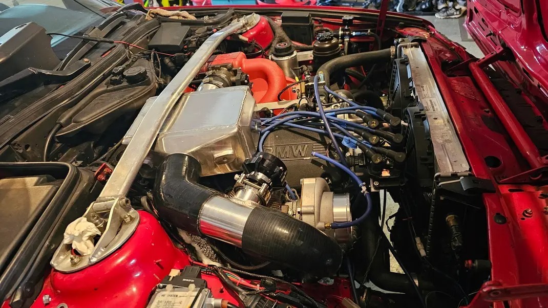
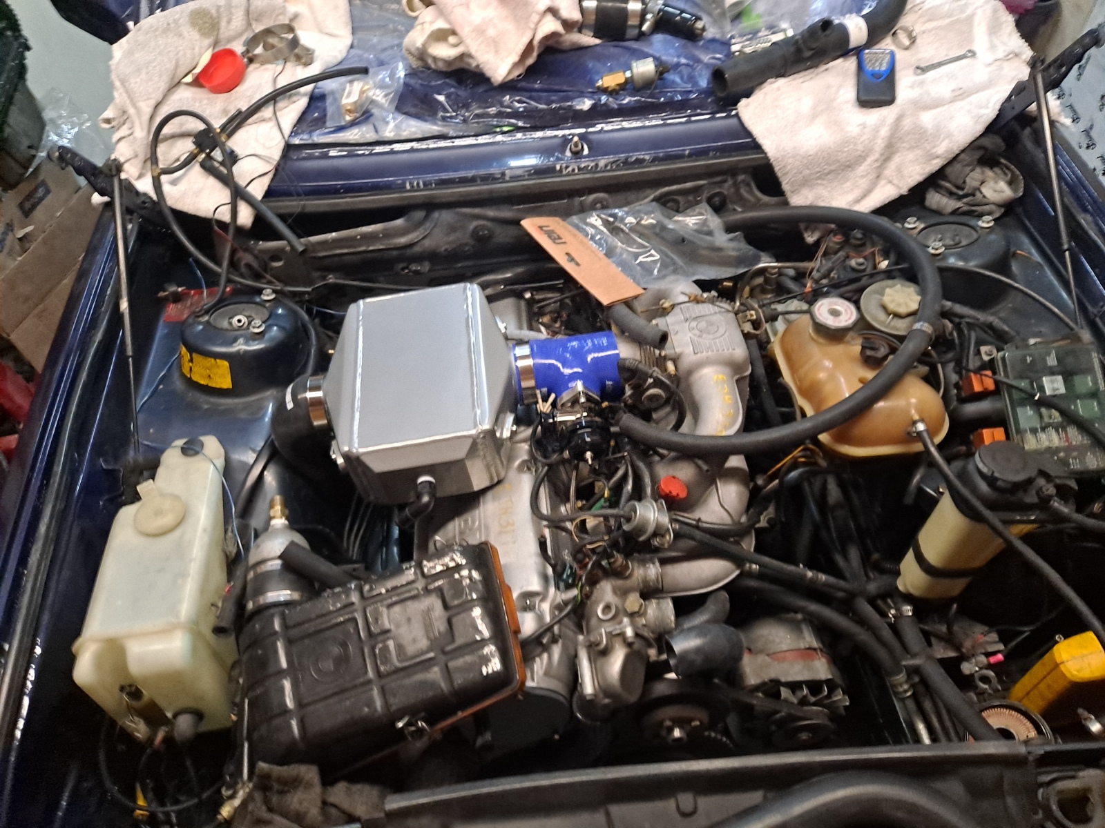
I got all of the intercooler parts installed, including IAT sensor and ICV port.  Here is how my IC looks by comparison. 

Image

Image
You can see the E36 radiator overflow tank. It seems like a good spot to have it mounted there near the battery if I can get the system to bleed. I will try it there with an air bleed line from the top of the heat exchanger. But I will monitor it to see if I need to somehow add a bleed line at the IC because of it being the system high point.


In some ways it seems this car is fighting me a little bit, so  I took a bit of time to focus on other things like children's sports, work and other personal things.

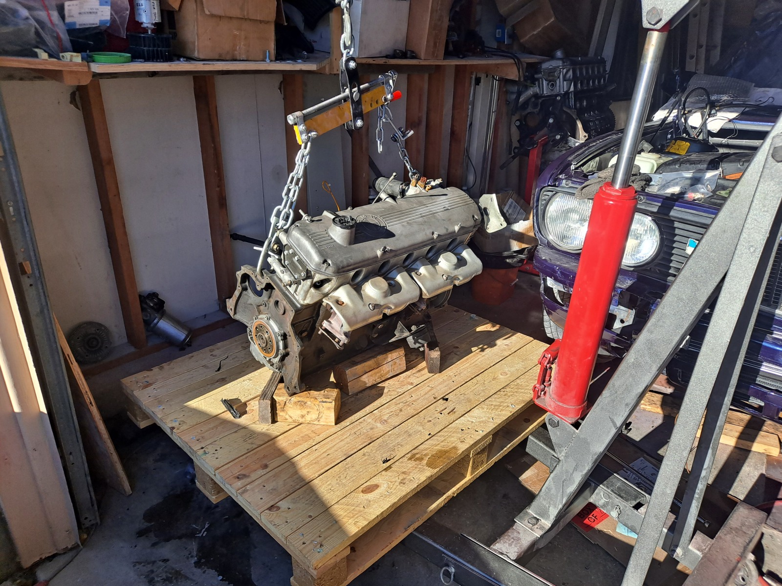
My euro 635 got wrecked last fall, so I pulled the engine, crated it and sold it last month. Here the m90 was on the pallet strapped down. I still have a few parts but it added an extra distraction to my plate as far as projects go. 

Image

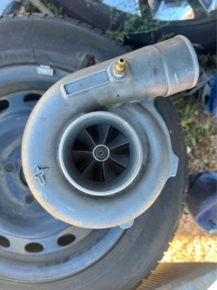
I also bought a turbonetics turbo that would mount up to this manifold because it was cheap (less than $200). IT appears to be a slightly smaller turbo than the TCD I have, but no marking so I had to check it by measurements. 57mm compressor, "O" trim turbine instead of 60mm compressor and "P" trim turbine, but would work at my boost levels of 1bar or less (and with the on-center housing).
Image

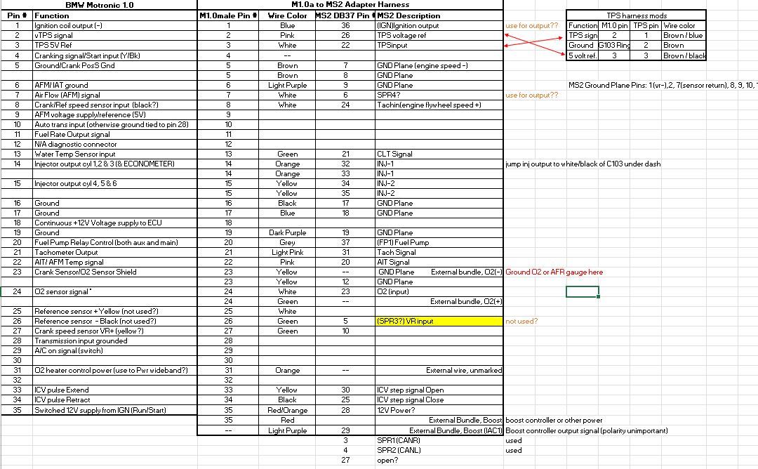
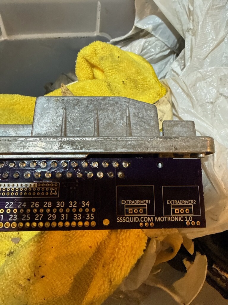
I aldo bought a SSSQuid M1.0 adapter. This would allow me to wire in an engine harness adapter and then run an E28 with megasquirt. I have the spare megasquirt already and an old harness if I wanted to try this out. Just the ms2 unit needs some finish work in wiring. It would be nice to have a spare unit that I could just plug in and run, but my main decision is should it be based on wasted spark or the original stock coil that coudl retrofit on my '88 auto 535i
Image

Small progress has been ongoing, though nothing flashy.

I ended with some checking of pump sizing.I am expecting no more than +30F IAT temps even when running hard with the sustained boost. So theoretically I could take the car to the local road course and not worry about IAT's. 
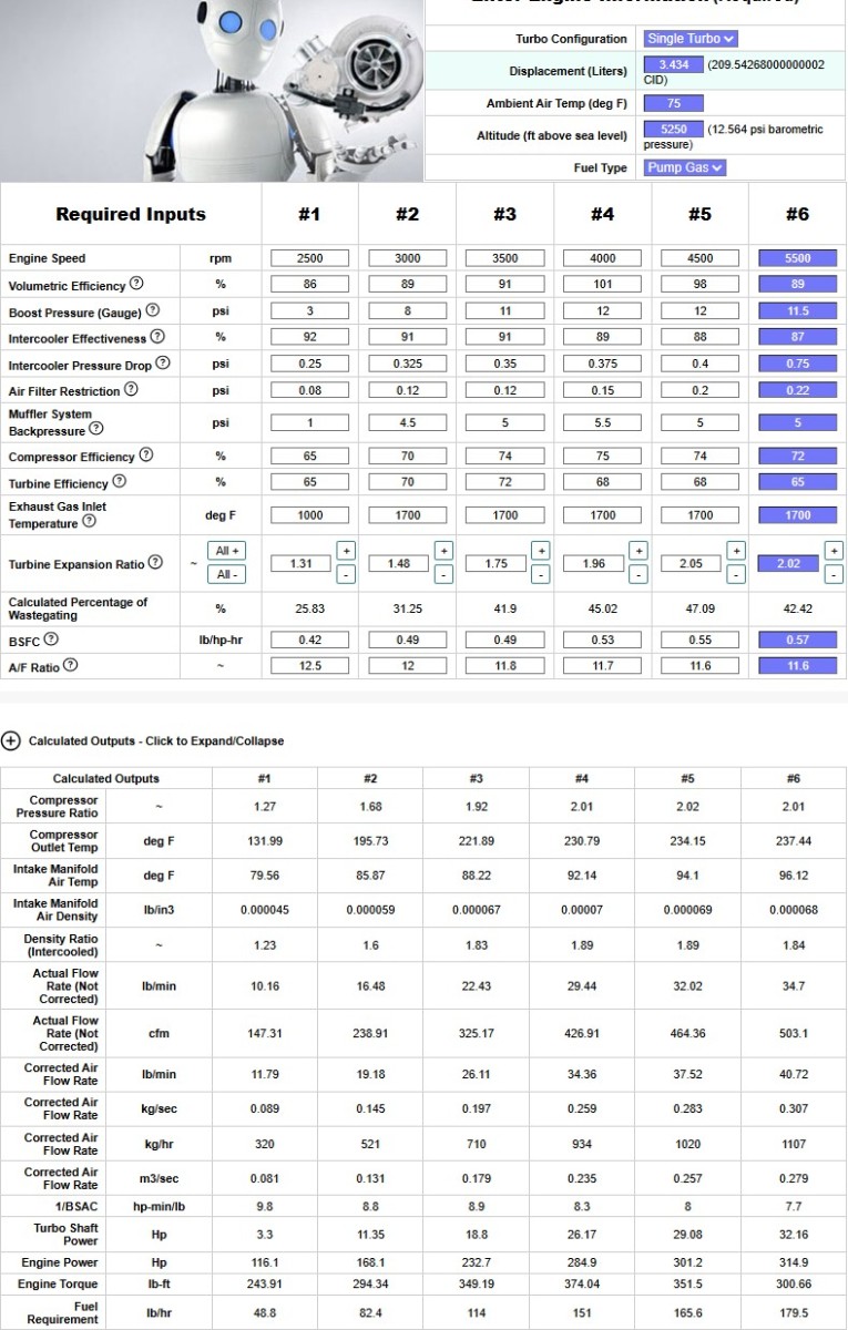
AI wasted some of my time estimating number for cooling, power, difference from A2A vs W2A, but MatchBot really was better for me to estimate with.

Image

This power estimate falls inline with torque curves and suggests in overall power the A2A would be pretty similar. But in boost response and cooling consistency W2A is generally going to be better, with an optimized acceleration due to a higher torque curve.

I did get the clutch supply line installed and yesterday got the slave bled enough for a little bit of pedal. I don't have full stiff pedal but partial pedal that doesn't sit at the floor. I am not sure is clutch master is leaking or if there is air in the system or if somehow the clutch fork isn't sitting in the right spot.

Transmission is sitting in the car but needs to be fully installed with hardware once I am sure the clutch pedal is fully operational. Then I can install the shifter, driveshaft, hoses and radiator. That including connecting the IC hoses, but I have them effectively done. 

I started on wiring and need to figure out how to remove the ignition lock. The switch is accessible, so I can play with electrical. I need to finish wiring (gauges/pump control), headlights, main IC pump and reinstall the MS2 control box. I was also considering wasted spark so will have to modify the board. I was also considering adding VSS speed into the megasquirt for datalogging.


I'd like to get a number of these things done or functional before attempting to start the engine.

Then I need to resolve title issues because I need VIN verification since the car was out of state. I need to trailer the car for this, or have it running for an Etest a couple of miles own at the inspection station.

Re: Homebrew Turbo e28 - 2026+ Update W2A

Posted: Jun 06, 2026 1:12 PM
by turbodan
That's a good sized core, I would be surprised to see IAT getting out of hand with that setup. My system is working without a reservoir or a bleed at the moment but there are bubbles trapped in the system that a reservoir would eliminate. I have one on order and will probably do that up in the next week. I don't know what to expect as far as self bleeding but I am assuming that the pressure differential will be sufficient if I run a bleed from the top of the intercooler and have the reservoir tee'd into the feed line going to the suction side of the pump. 

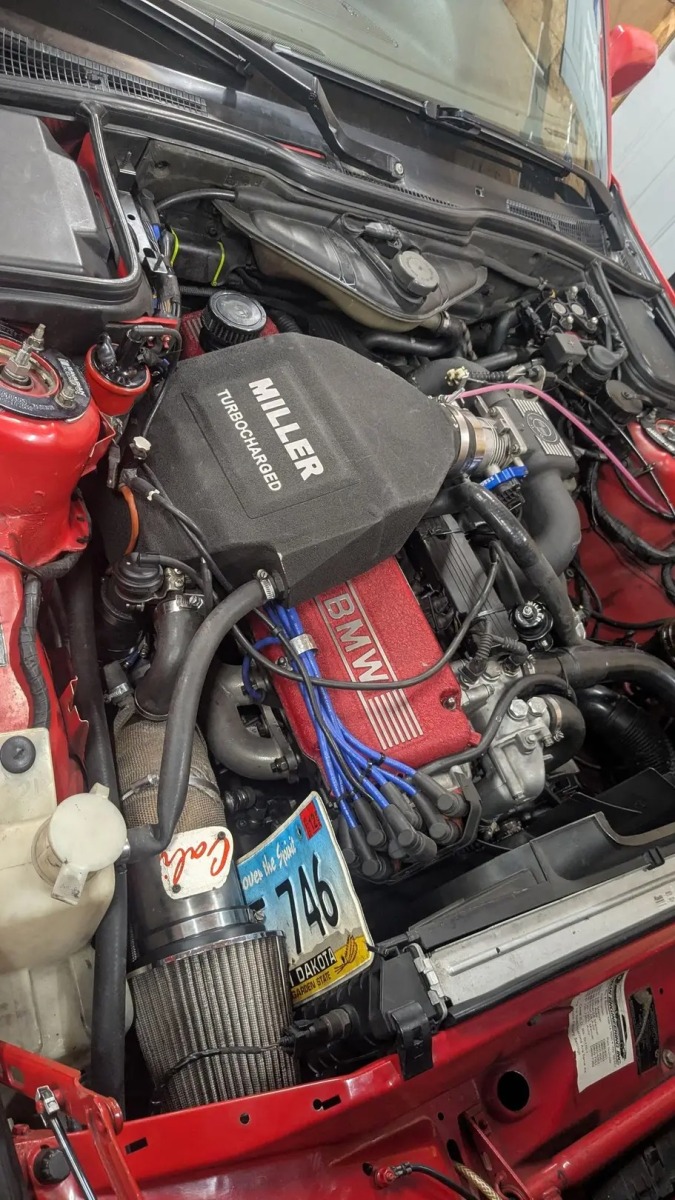
The guy with the license plates and Miller intercooler has a serious kink in one of his water lines, that'll ruin the fun pretty quick.

Re: Homebrew Turbo e28 - 2026+ Update W2A

Posted: Sep 04, 2026 12:43 PM
by tschultz
In June my wife and I had another child, so that pretty much halted progress even though I was home.

I did get a chance to get back to the car a little bit recently and work for a few hours. And I just realized it has been 1 year now!

I was able to clean up the wiring for the headlights and turn signals. I need to check the turn signal switch now, but at least they are mounted in the valance and wired. The city lights and euro lights are working, though I need to finish the last steps of wiring there.

I also started organizing the wiring for the megasquirt gauges and sensors. I'd like to spend some extra time pulling power and arranging the wiring nicely. So far i have the gauges positioned above the center vent. As a last steps i will probably be labeling everything and  trying to get connectors for easier disconnect. Possibly vss speed signal input to ms2, coming out of the instrument cluster. Not totally sure if it will work.


I also have 4 wires sitting in place to run the wasted spark setup and the wire to operate the circulating pump with pwm control. The controller should sit down by the headlight switch.
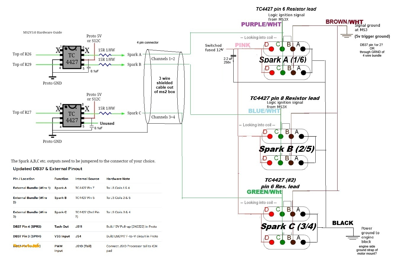
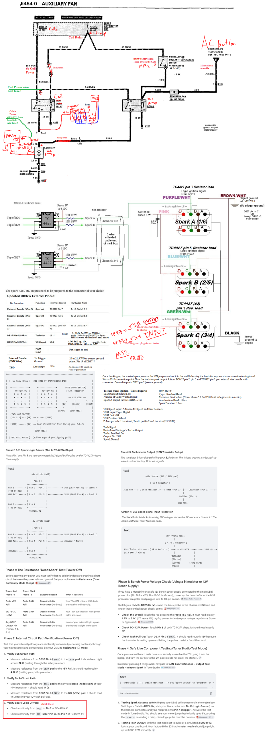
Here is my revised schematic and details. some AI prompts to help me define the wiring, but I need to check this through for the proto circuits for vss speed input and the tach output.

Image 


I also started moving some interior pieces in to the chassis, but I am still in process as I work through wiring.
More slow progress to come!