External links now open in a new browser tab - turn this off in your UCP - Read more here.

Maytag's M20B27 'e2i' Engine Build Thread (87 528e)

E28 technical advice asked and given! Troubleshooting, modifications and more.
tig
Posts: 9396
Joined: Mar 18, 2013 6:25 PM
Location: Durango
Contact:

Re: Maytag's M20B27 'e2i' Engine Build Thread (87 528e)

Post by tig »

Kyle in NO wrote:Sure, if you don't care about having the Super Eta dual exhaust, which would be a foolish move.
FWIW, I just measured the Eta and Super Eta manifolds and the inner dimensions are identical.

The Super Eta exhaust is dual all the way back.

The Eta exhaust is dual to just after the cat.

I think I'm going to just use the downpipe from the Eta and fab up a dual (or single 2.5") from the resonator back.

(I have not been able to source a Super Eta downpipe that isn't missing a part like mine is).

Image

Initially, so I can get the car off the lift as soon as possible, I'm just going to use the Eta exhaust as-is, as was the original plan.
duggi
Posts: 2417
Joined: Apr 26, 2007 4:45 PM
Location: San Francisco, CA
Contact:

Re: Maytag's M20B27 'e2i' Engine Build Thread (87 528e)

Post by duggi »

FWIW I'm using my eta exhaust as-is currently and it chokes the engine above 5k, noticeably.

I have a factory 535i exhaust (everything behind the cat) sitting in my garage -- I was considering the OBX headers, but your measurements are worrying...did you get a chance to re-measure the ID on those rather than the OD for a direct comparison to your ID measurements of the stock pieces?
tig
Posts: 9396
Joined: Mar 18, 2013 6:25 PM
Location: Durango
Contact:

Re: Maytag's M20B27 'e2i' Engine Build Thread (87 528e)

Post by tig »

duggi wrote:FWIW I'm using my eta exhaust as-is currently and it chokes the engine above 5k, noticeably.

I have a factory 535i exhaust (everything behind the cat) sitting in my garage -- I was considering the OBX headers, but your measurements are worrying...did you get a chance to re-measure the ID on those rather than the OD for a direct comparison to your ID measurements of the stock pieces?
Super Eta/Eta manifolds have an inlet ID of 42mm and an outlet ID of 33mm:

Image

Image

The OBX M20 headers have an inlet ID of 38mm and an outlet ID of 33mm :

Image

Image

Good to know about the choking...
Karl Grau
Posts: 9718
Joined: Mar 10, 2006 7:34 PM
Location: Sandy Eggo

Re: Maytag's M20B27 'e2i' Engine Build Thread (87 528e)

Post by Karl Grau »

duggi wrote:your measurements are worrying...did you get a chance to re-measure the ID on those rather than the OD for a direct comparison to your ID measurements of the stock pieces?
Because I'm now recently a welder owner with 45 minutes of experience, I've resurrected the e30 exhaust project. I don't know if it carries over to e28s, but all of the IDs of the Hartge pieces and stock pieces for the e30 are 45mm ID.

Image
duggi
Posts: 2417
Joined: Apr 26, 2007 4:45 PM
Location: San Francisco, CA
Contact:

Re: Maytag's M20B27 'e2i' Engine Build Thread (87 528e)

Post by duggi »

cek wrote:
duggi wrote:FWIW I'm using my eta exhaust as-is currently and it chokes the engine above 5k, noticeably.

I have a factory 535i exhaust (everything behind the cat) sitting in my garage -- I was considering the OBX headers, but your measurements are worrying...did you get a chance to re-measure the ID on those rather than the OD for a direct comparison to your ID measurements of the stock pieces?
Super Eta/Eta manifolds have an inlet ID of 42mm and an outlet ID of 33mm:

Image

Image

The OBX M20 headers have an inlet ID of 38mm and an outlet ID of 33mm :

Image

Image

Good to know about the choking...
I'm noticing that you seem to have the inlet and outlet identified backwards above with regard to the super-eta manifolds... Inlet ID: 33mm and Outlet ID: 42mm. And it also seems that you have taken your measurement from the wrong mark on the caliper with regard to your OBX headers, so perhaps Inlet ID: 38mm and Outlet ID: 42mm (from what I see in the photo).

I just measured my husband's e30 Hartge H27 headers (they're in our spare room, waiting for his future engine build) with my cheap calipers (I just ordered better ones on Amazon and will follow-up with photos later in the week) and they seem to be -- [updated 1/3/17] Inlet ID: 37mm and Outlet ID: 46mm.

I have some m20b25 manifolds somewhere, but can't remember where..I'll try to find them to add to the measurements below (summarizing this all in one place for ease of comparison):

Eta/Super-Eta Manifolds - Inlet ID: 33mm - Outlet ID: 42mm
OBX M20-e28 Headers - Inlet ID: 37mm - Outlet ID: 42mm
Hartge e30 H27 Headers - Inlet ID: 37mm - Outlet ID: 46mm

It seems to me, that from these measurements, the OBX headers represent a significant increase in the inlet ID over the stock or even Hartge options. I'd also like to measure my stock NON-super eta manifolds after I get them off to see how they stack up...
Last edited by duggi on Jan 03, 2018 9:02 PM, edited 3 times in total.
tig
Posts: 9396
Joined: Mar 18, 2013 6:25 PM
Location: Durango
Contact:

Re: Maytag's M20B27 'e2i' Engine Build Thread (87 528e)

Post by tig »

You are correct that I had inlet/outlet backwards on the manifolds.

Obx Inlet ID is 37mm.

Obx Outlet ID is 42mm.

I measured my NON-super eta manifolds and they are exactly the same ID dimensions as the Super's.
tig
Posts: 9396
Joined: Mar 18, 2013 6:25 PM
Location: Durango
Contact:

Re: Maytag's M20B27 'e2i' Engine Build Thread (87 528e)

Post by tig »

Blunt sent me the wrong flywheel bolts. Dammit. I was hoping to have this all put together by tomorrow afternoon.

Image

I did discover my crank has the old school, felt-based pilot bearing. I also discovered that 12 grain bread with little seeds works fine getting pilot bearings out.

Image

Question: How far should the pilot bearing be pressed into the crank? When I did this before I just made it flush. But I noticed the old bearing was pressed in about 2-3mm.
duggi
Posts: 2417
Joined: Apr 26, 2007 4:45 PM
Location: San Francisco, CA
Contact:

Re: Maytag's M20B27 'e2i' Engine Build Thread (87 528e)

Post by duggi »

I found a German TÜV Document for the Hartge H27 which had detailed drawings of the exhaust system, including measurements. I can't verify if it's ID or OD measurements (I think OD), but will compare what's here to our headers when my calipers arrive.

Image
tig
Posts: 9396
Joined: Mar 18, 2013 6:25 PM
Location: Durango
Contact:

Re: Maytag's M20B27 'e2i' Engine Build Thread (87 528e)

Post by tig »

cek wrote:Blunt sent me the wrong flywheel bolts.
To be clear, Blunt sent me the flywheel bolts I ordered, so this was not his fault: 11 22 2 243 051 (12x50mm for dual-mass flywheels).

I don't have a dual-mass flywheel, so I needed to order 11 22 7 805 885 (12x28mm).
duggi
Posts: 2417
Joined: Apr 26, 2007 4:45 PM
Location: San Francisco, CA
Contact:

Re: Maytag's M20B27 'e2i' Engine Build Thread (87 528e)

Post by duggi »

My calipers came today, so I took measurements and pics to update the information on the Hartge H27 headers (I've edited the post above with the accurate info):

Intake ID: 37mm
Intake OD: 40mm
Outlet ID: 46mm
Outlet OD: 50mm

This matches the information from the Hartge document I posted above...as well as points out how hard it is to measure without the proper tools. It also makes me think that the OBX headers are a really appropriate match for the 2.7i conversion. The 42mm outlet size shouldn't be an issue if you were already ok using the super-eta downpipes, which is the conventional solution.

Final mashup:
Eta/Super-Eta Manifolds - Inlet ID: 33mm - Outlet ID: 42mm
OBX M20-e28 Headers - Inlet ID: 37mm - Outlet ID: 42mm
Hartge e30 H27 Headers - Inlet ID: 37mm - Outlet ID: 46mm

Pics:

Image

Image

Image

Image

Image

Image
tig
Posts: 9396
Joined: Mar 18, 2013 6:25 PM
Location: Durango
Contact:

Re: Maytag's M20B27 'e2i' Engine Build Thread (87 528e)

Post by tig »

Thanks duggi.
tig
Posts: 9396
Joined: Mar 18, 2013 6:25 PM
Location: Durango
Contact:

Re: Maytag's M20B27 'e2i' Engine Build Thread (87 528e)

Post by tig »

Whew. That was a lot of work. I feel like I was rode hard and put away wet. Probably doesn't help that I played soccer for almost 2 hours this morning and then was so focused on wrenching I forgot to eat anything all day.

If you saw 
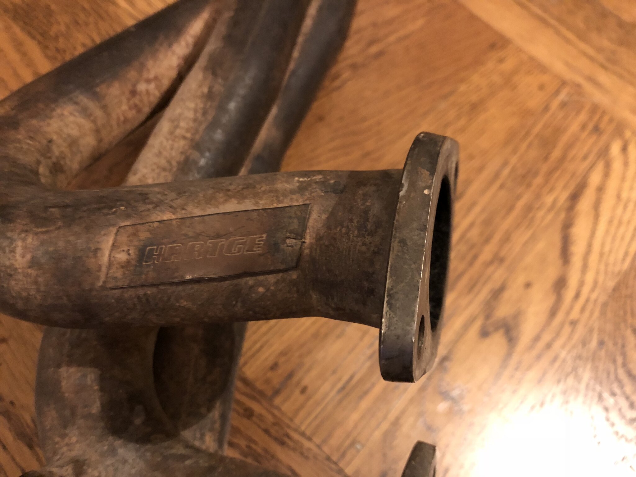
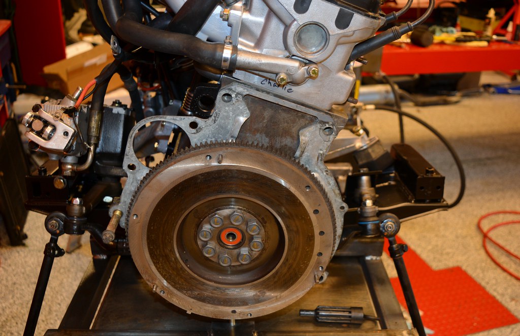
this thread you know that I am struggling with the fact the clutch pedal disengages clutch too high and how to resolve. I learned a bunch (and discovered there are two variants of getrag 260/5; one with a 5mm deeper bell-housing). But I am still unsure why my engagement point is wrong. I'm moving ahead with what I think will address it: Switching to the shorter variant of the throw out bearing.

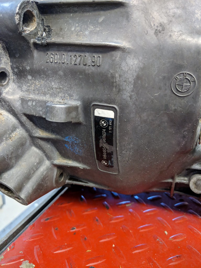
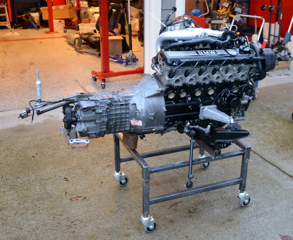
For future reference (for me when I forget and search this thread to remember), here's the specs on the transmission in this car:

Transmission on Maytag
PN on Bellhousing: 260.0.1270.90
VIN: WBAAB5407H9696074
Model: 1986-07-31 US 325E (not a 528e as I had previously thought)
Housing PN from RealOEM: 23111222657
T/O Bearing PN from RealOEM: 21517521471
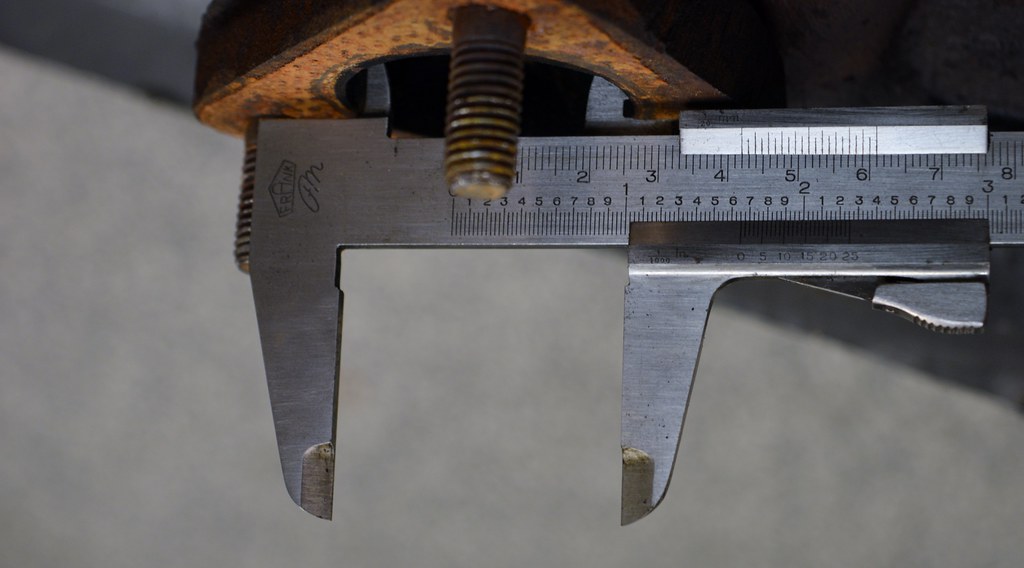
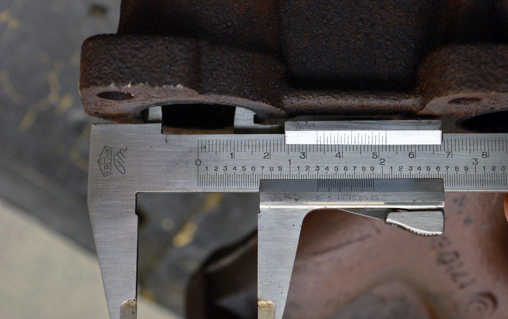
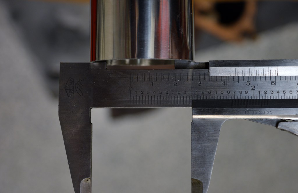
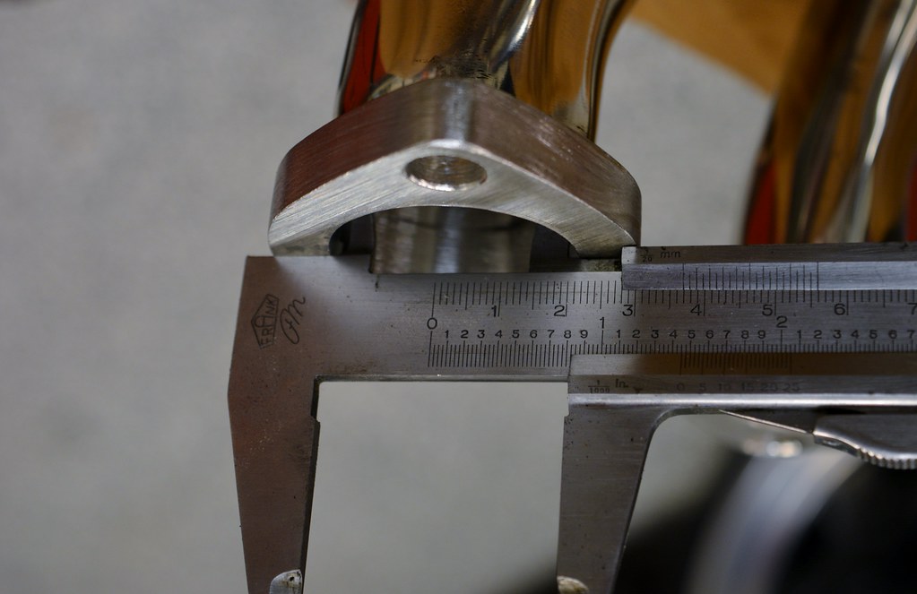
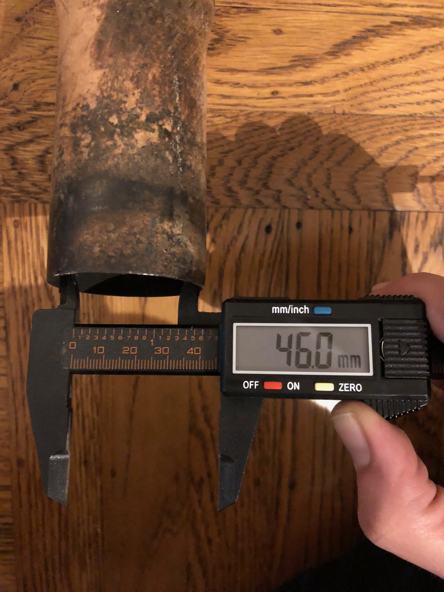
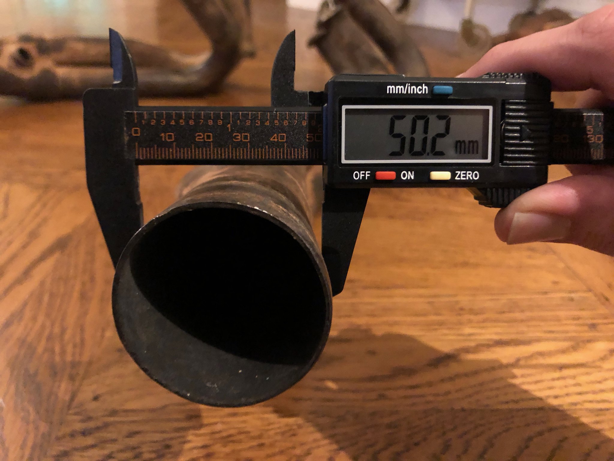
OAL (output shaft to bell-housing face): 55mm
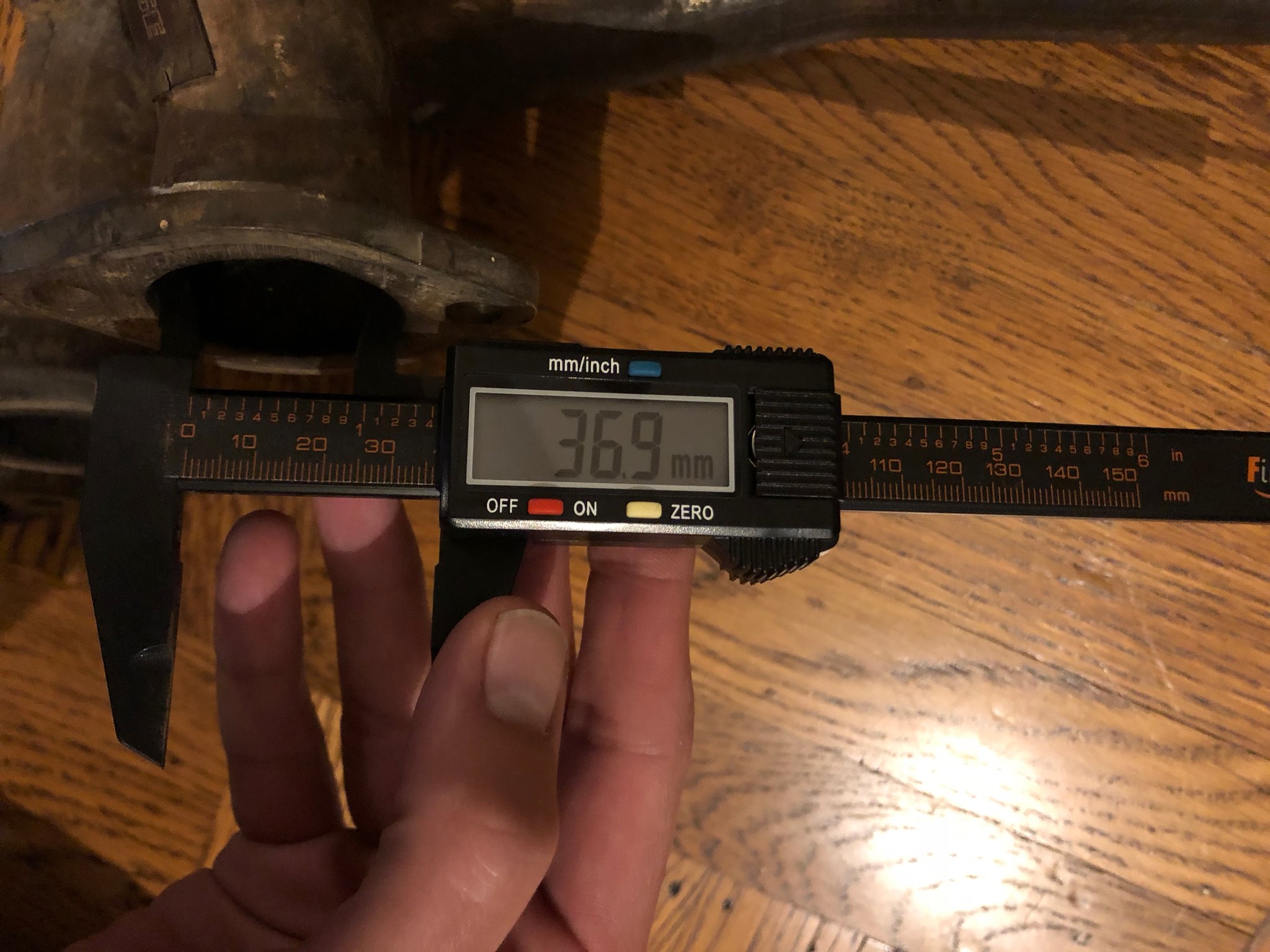
Bell-housing length (rear casing front to bell-housing face): 37.5mm
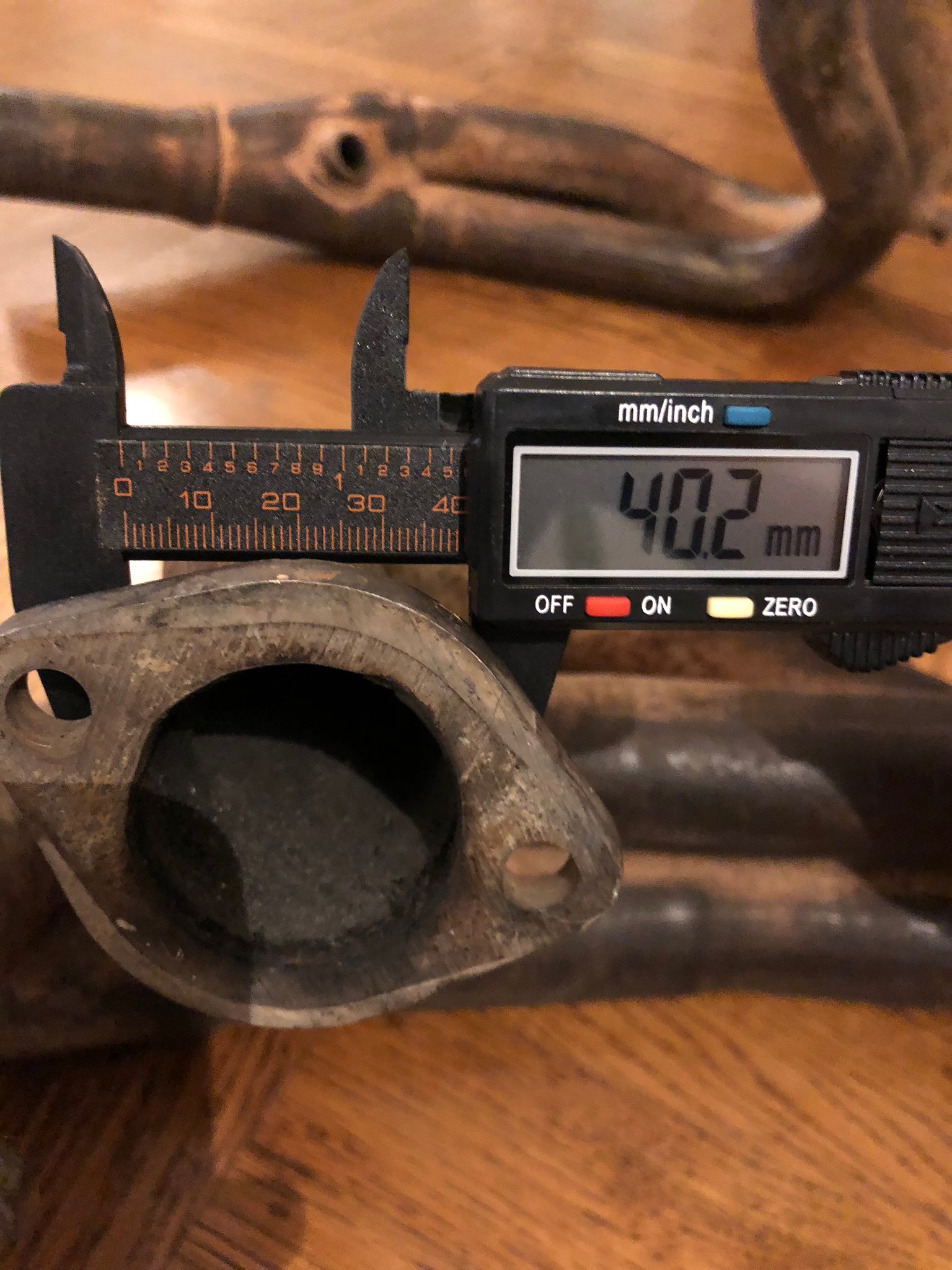
Bell-housing depth (slave face to bell-housing face): 17mm

Image

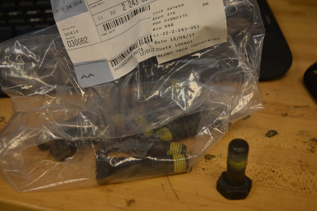
Got the right flywheel bolts from blunt.
Image

Image

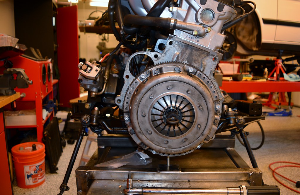
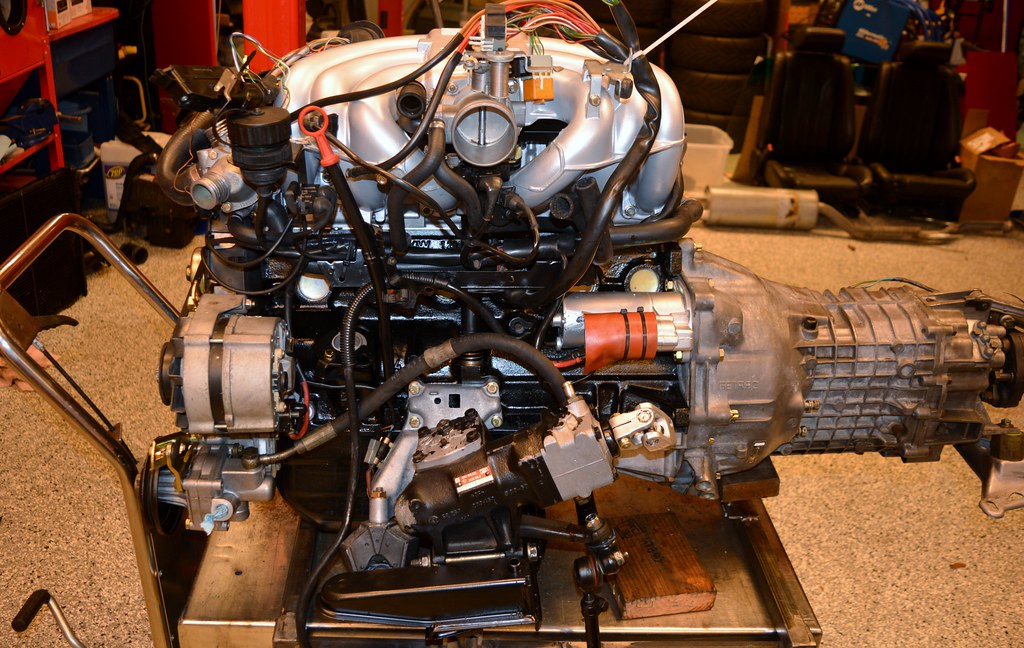
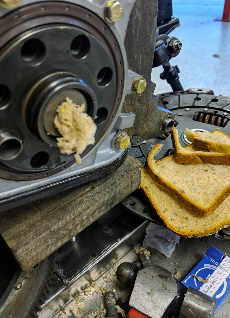
Hooked transmission up. Used the right greases on the splines and TO bearing.
Image

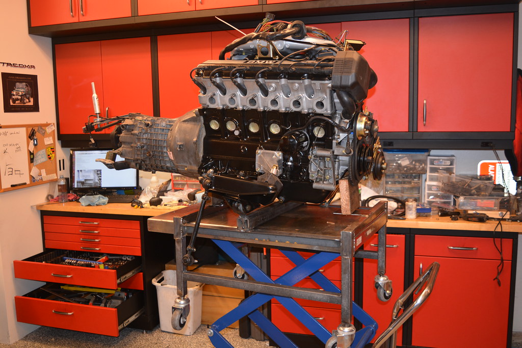
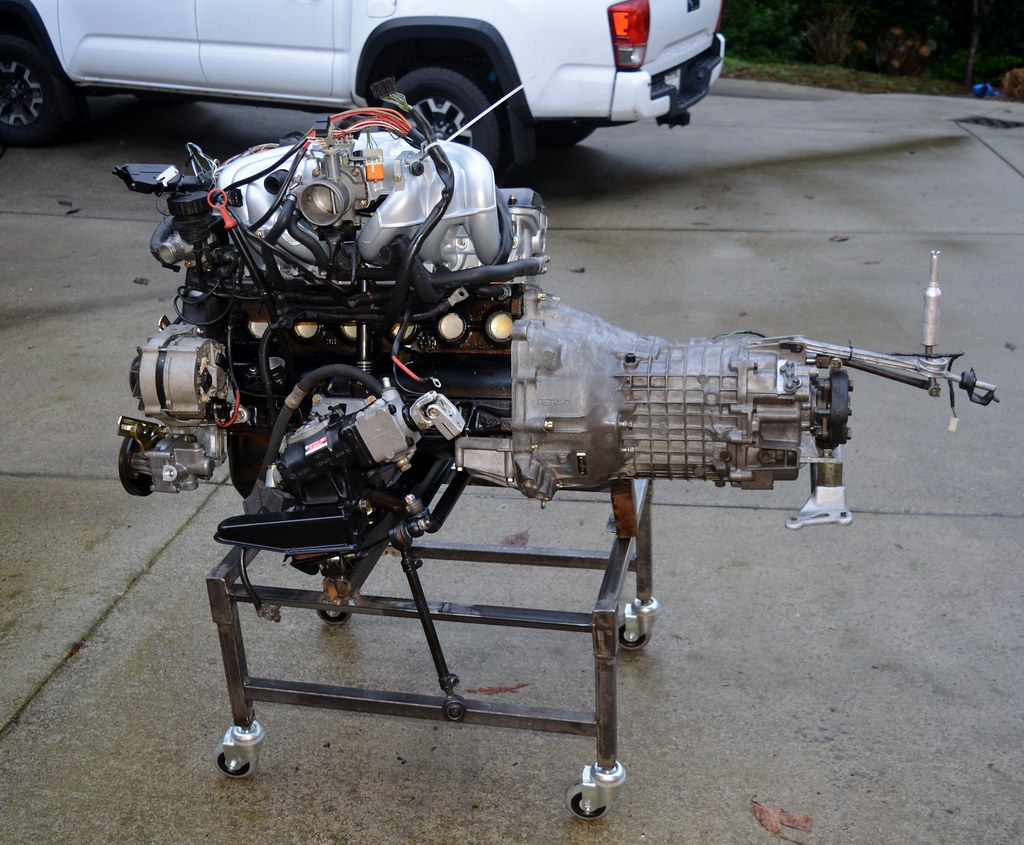
Tried another test-fitting lifting the engine and transmission up through the bottom with the lift table. Realized everything would go much more smoothly if I modified my cradle to mount the assembly further forward; will give more clearance with the front of my 4-post lift.

Always love a chance to get the welding table out!
Image

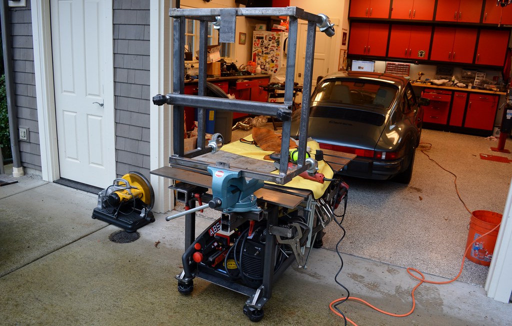
A bit of the grinding wheel and some fresh welds and I set the engine/tranny back on. Much better balance too.
Image

Image

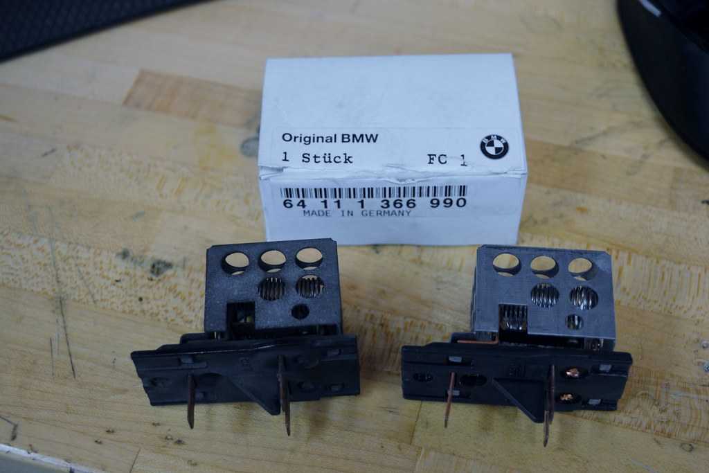
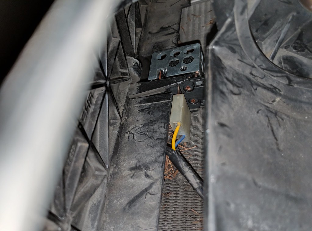
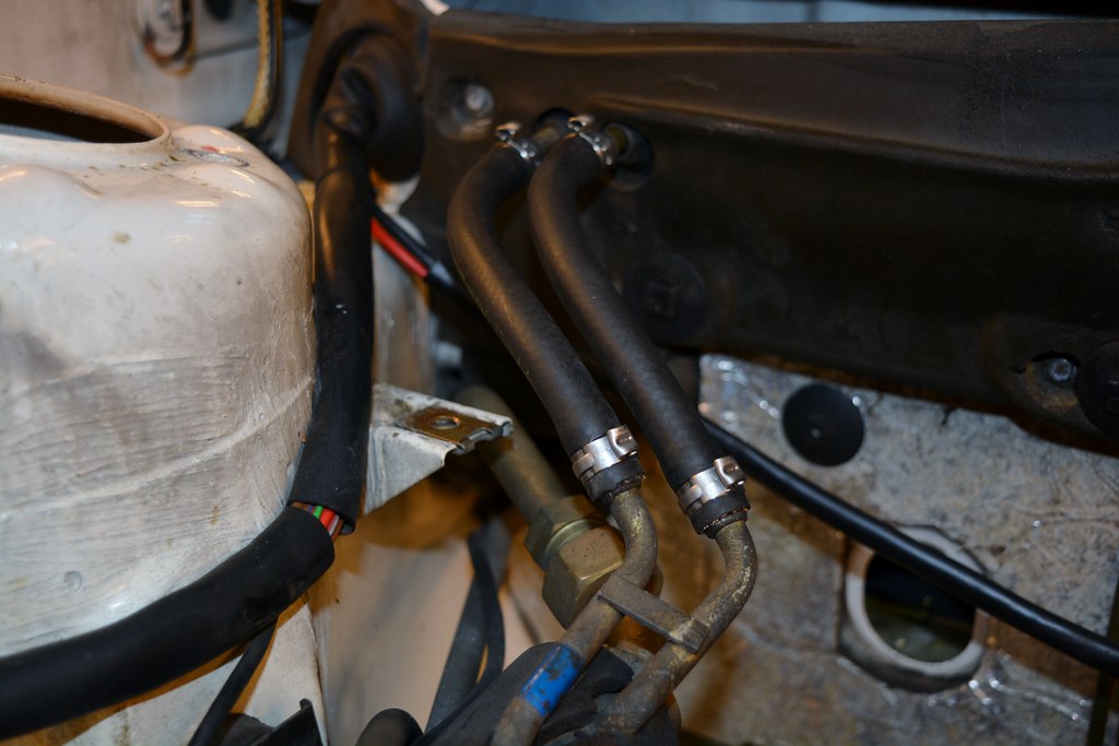
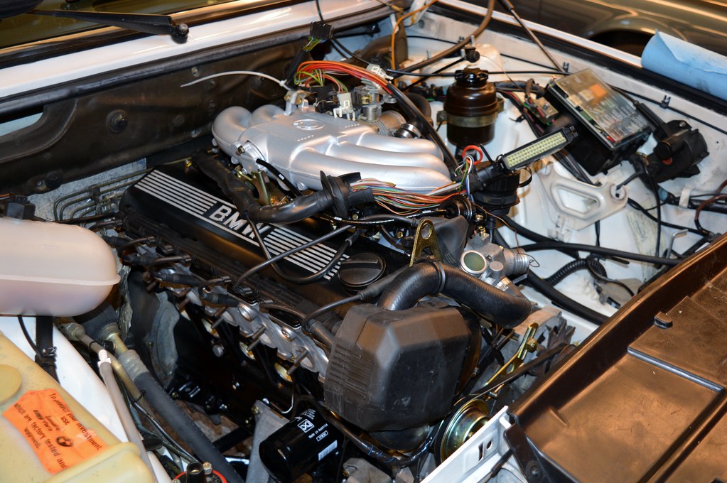
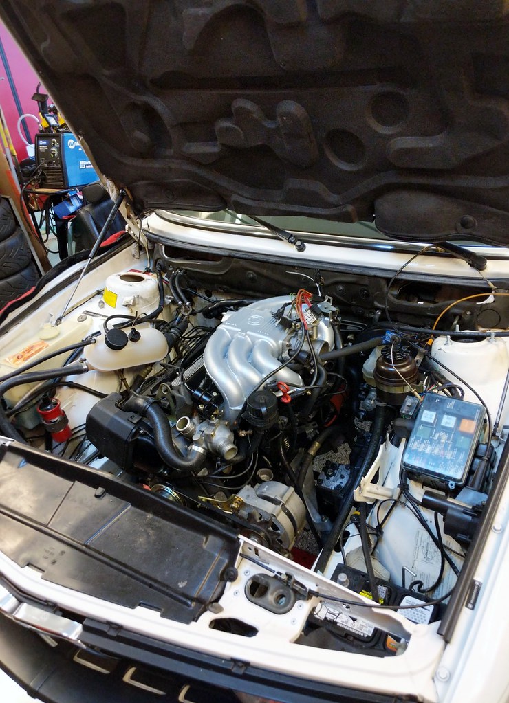
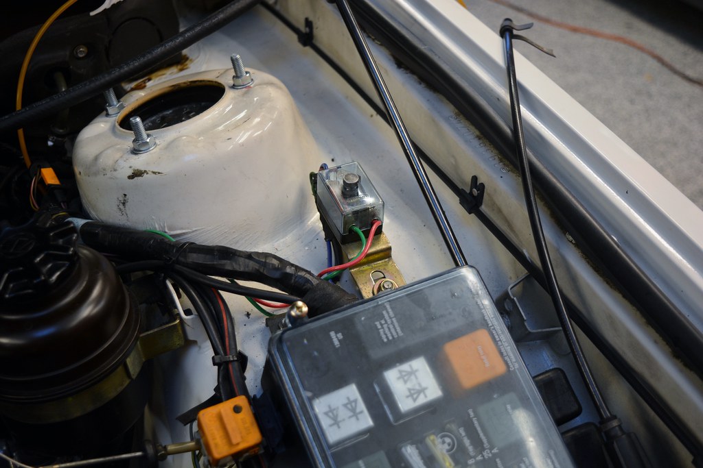
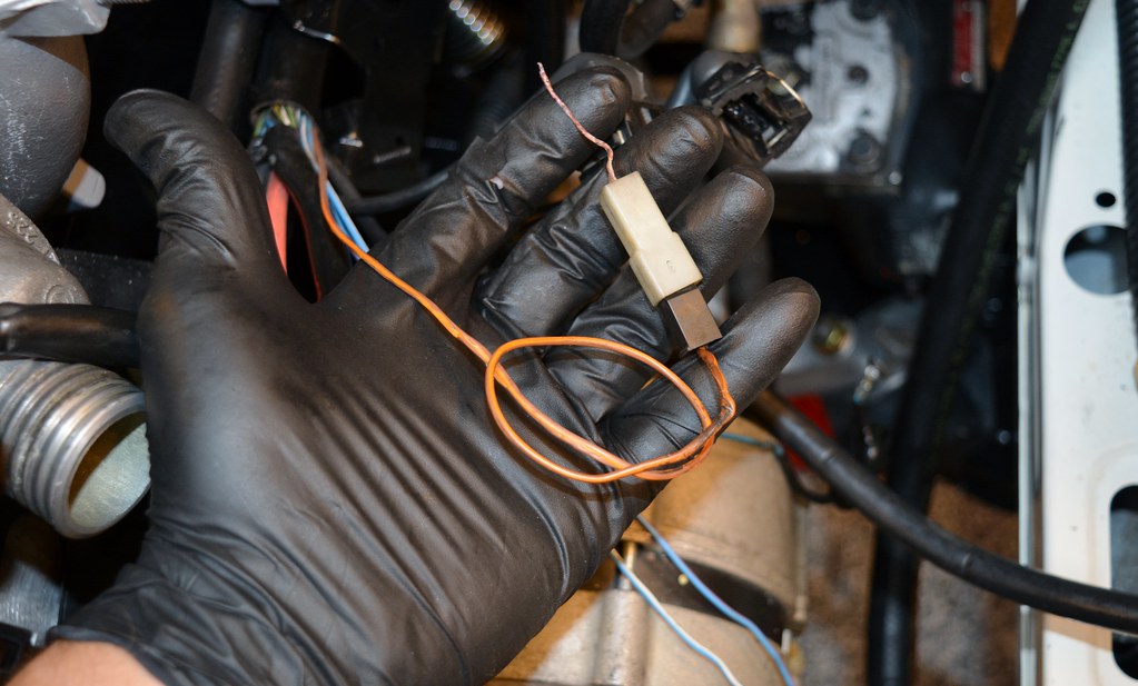
Got the starter installed and hooked up the PS hoses. Everything that needs to go together before it goes in the car is now done. But before I can put it in I need to do a few more things in the engine bay, including installing a new resistor pack. You'll recall my heater fan "races" to full speed at random times any time it is on. I expected the old resistor pack to look super rusty or destroyed. It actually looks fine. Hopefully this actually fixes the problem.

Image

Image
tig
Posts: 9396
Joined: Mar 18, 2013 6:25 PM
Location: Durango
Contact:

Re: Maytag's M20B27 'e2i' Engine Build Thread (87 528e)

Post by tig »

Got the heater resistor pack in. This thread helped immensely by enabling full visualization of how it slides into place. http://www.mye28.com/viewtopic.php?f=3&t=130884

After I took this pic, I used a vacuum to clean the weeds out.
Image

Before:
Image

After:
Image

When I replaced the fuel lines I skipped these two because I was lazy. Always felt bad about that. Fixed.
Image

Two buddies came by today and helped me manoeuvre the engine and tranny into place as I used a combination of the lift and lift table. It took a bit of finagling, but in the end went smoothly...

Ta-fucking-da!
Image

Image

Put oil in and then went to lunch. When I got back there was a big puddle of oil on the floor.

I put the wrong o-ring in for the oil level sensor. It was obvious once I pulled it and looked. I *knew* I had bought one, so I poked around and found this little baggie. Whew.

Image

Fuel lines, PS lines, and most electrics are connected. Then I ran out of time for the weekend. Glad I kept the fuse box from the Super Eta I parted out so that I could have this bracket.

Image

Should be running next weekend!

Specs:
  • M20B27 block bored "40 over" (86mm)
  • Custom pistons: (9.5:1 compression)
  • Max-speeding 130mm h-beam rods
  • 885 head with 3-sided valve grind
  • Stock camshaft
  • Cometic .086" thick, .86mm bore MLS Head Gasket
  • Arp studs
  • 325i injectors
  • 173 ECU (stock for now)
  • Exhaust: TBD
Last edited by tig on May 21, 2018 1:43 AM, edited 2 times in total.
tn535i
Posts: 5590
Joined: Jul 14, 2006 1:30 PM
Location: Middle Tennessee

Re: Maytag's M20B27 'e2i' Engine Build Thread (87 528e)

Post by tn535i »

Personally I think that fuel cooler is a whole lot of contraption with potential for leaks in some places I would not want leaks. I would eliminate that.

Otherwise, I'm really enjoying the work and progress. Good stuff.
duggi
Posts: 2417
Joined: Apr 26, 2007 4:45 PM
Location: San Francisco, CA
Contact:

Re: Maytag's M20B27 'e2i' Engine Build Thread (87 528e)

Post by duggi »

Congrats on getting the engine in the car!!! Bet it feels great to stand there looking at that! :D
ElGuappo
Posts: 8130
Joined: Feb 12, 2006 12:00 PM
Location: Sacramento, CA
Contact:

Re: Maytag's M20B27 'e2i' Engine Build Thread (87 528e)

Post by ElGuappo »

Seriously good thread filled with tons of excellent info.
I hope that some day this summer my 528 e2i can feel bad about itself compared to this car... :laugh:

Re: gasket material on the fireall, what kind of insulation did you use?
tig
Posts: 9396
Joined: Mar 18, 2013 6:25 PM
Location: Durango
Contact:

Re: Maytag's M20B27 'e2i' Engine Build Thread (87 528e)

Post by tig »

ElGuappo wrote:Seriously good thread filled with tons of excellent info.
I hope that some day this summer my 528 e2i can feel bad about itself compared to this car... :laugh:

Re: gasket material on the fireall, what kind of insulation did you use?
Thanks for the kind words.

For this car I left oe firewall in tact as it is in ok shape.

See vlad's thread for what NOT to do. See Vince's m535 thread for how to do it right.
ElGuappo
Posts: 8130
Joined: Feb 12, 2006 12:00 PM
Location: Sacramento, CA
Contact:

Re: Maytag's M20B27 'e2i' Engine Build Thread (87 528e)

Post by ElGuappo »

Should've been more specific, but I've got the 'sick-stupid' brain going...
The panel above the firewall with the fuel lines, that covers the heater blower.
What kind of insulation tape/gasket material did you use? Standard foam or a neoprene kind of thing?
Thanks
tig
Posts: 9396
Joined: Mar 18, 2013 6:25 PM
Location: Durango
Contact:

Re: Maytag's M20B27 'e2i' Engine Build Thread (87 528e)

Post by tig »

ElGuappo wrote:Should've been more specific, but I've got the 'sick-stupid' brain going...
The panel above the firewall with the fuel lines, that covers the heater blower.
What kind of insulation tape/gasket material did you use? Standard foam or a neoprene kind of thing?
Thanks
I bought one each of every roll O'Reilly sold. 1" wide, 3/16 thick (I think), foam. Seemed like a good idea
tig
Posts: 9396
Joined: Mar 18, 2013 6:25 PM
Location: Durango
Contact:

Re: Maytag's M20B27 'e2i' Engine Build Thread (87 528e)

Post by tig »

I'm going to drink heavily tonight. Because I seriously effed up.

On the 88 528e Super-Eta harness, there is a ground wire that goes directly to the negative terminal on the battery. G103.

I didn't notice this, or think it through, or something, because guess where I hooked it up to?

I hooked it up with the positive wires on the positive terminal of the battery.

I was going to spin the motor over using Pins 11/14 in the diagnostics port, to ensure the starter was working and verify I was getting oil pressure.

I hooked up the battery (with a charger on it...) and I got smoke. Lots of it. Some from what looked like the timing belt area and some from the oil level sensor, where the ground wire melted all the way through. There was a little pop from down there and it was either that wire going, or the oil level sensor going bad.

So now I'm wondering just how badly I damaged my wiring harness. I have been tracing through the ETM for an hour trying to see where G103 goes to and where in the harness I should look to see what I fried.

I think, to be safe, I'm going to need to completely replace the SuperEta harness... I have another, but it's not in as good of shape.

Heavy sigh.

Image

Image

In good news, I was able to get the engine to turn over with the starter (after putting G103 on the negative terminal of the battery).

Anyone know where those two wires in G103 actually go? In looking at the ETM, they go a LOT of places. FWIW, my ECU was NOT plugged in (thank goodness).
tig
Posts: 9396
Joined: Mar 18, 2013 6:25 PM
Location: Durango
Contact:

Re: Maytag's M20B27 'e2i' Engine Build Thread (87 528e)

Post by tig »

In studying the ETM I have identified all the components that connect to the BR wire going to G103 that might have been destroyed by having +12V with high amps going through them the wrong way. Many potential components were 'spared' (i think) because the ECU was not connected.

This diagram shows some:

Image

Not-affected:
- ECU (wasn't connected)
- O2 sensor (wasn't connected)
- Diagnostic connector (cap was off and nothing was connected)

Affected:
- Oil Level Sensor - for sure affected, as the ground wire completely melted and I heard it pop).
- Coolant temp sensor - if it's not fried, then the .5br wire to it probably is. Is the coolant temp sensor normally open? If so it may be ok.

More:
Image

Affected:
- Coil - it's very possible the smoke I saw (lots of it) coming from the timing belt area was the 2.5 BK that goes to the coil, as it runs in front of the timing belt cover. This will be easy to verify. I have another coil so will swap in anyway.
- Cylinder Identification Sensor - Like the coil wire, it's entirely possible this wire got fried (it is part of the spark plug wires, meaning I will need to replace them). Also runs in front of the timing belt cover.
- Engine Speed Sensor - I bet this is toast for sure (or at least the wires leading to it).

All the wires I can find that go to G103 for the 88 MY are BR. But you'll note in the picture I posted above there's both a BR and a BR/Y wire in that bundle. I can't find ANY BR/Y wires in the ETM. Does anyone have any idea where that wire might go?

Replacing the harness with the other one I have will be a bear, but mostly time consuming. I'm hoping I can do it without taking the intake manifold off...
mooseheadm5
Beamter
Beamter
Posts: 23035
Joined: Apr 08, 2009 10:30 PM
Location: Charlottesville, VA
Contact:

Re: Maytag's M20B27 'e2i' Engine Build Thread (87 528e)

Post by mooseheadm5 »

Coil should be ok, the shield wire is what fried.
Coolant temp sensor is a resistor, but not designed to carry any load so it could be bad. You can ohm out both of these things to test them.
You can replace just the cylinder sync sensor on the plug wire if you can get a used one.

The other shield wires may have melted as well.

If they have a plug like the 325i harness does the harness can be replaced without pulling the intake.
tig
Posts: 9396
Joined: Mar 18, 2013 6:25 PM
Location: Durango
Contact:

Re: Maytag's M20B27 'e2i' Engine Build Thread (87 528e)

Post by tig »

mooseheadm5 wrote: If they have a plug like the 325i harness does the harness can be replaced without pulling the intake.
Thanks. Good insight.

Nope, the 528e Super Eta harness is not two-piece like the 325i harness. I actually have one of the injector harnesses for a 325i... a lot of good that's going to do me.
tn535i
Posts: 5590
Joined: Jul 14, 2006 1:30 PM
Location: Middle Tennessee

Re: Maytag's M20B27 'e2i' Engine Build Thread (87 528e)

Post by tn535i »

Shield wires should NOT have melted because as a shield it is only grounded at one end, the end you connected to the battery by mistake. So unless the shield wire was bare and touching something there should have been no current.

Something does not make sense to me when you describe the wires that cooked. Only things that could complete the circuit should have had current flow.
The CTS should have been open at the other end (No DME) so it should be OK. Same for the spark plug wire loom wire sensor and the coil.

The oil sensor is just a switch so the oil would have to be low and switch closed but that would send current somewhere I think. Maybe to other things connected to the check panel.
tig
Posts: 9396
Joined: Mar 18, 2013 6:25 PM
Location: Durango
Contact:

Re: Maytag's M20B27 'e2i' Engine Build Thread (87 528e)

Post by tig »

tn535i wrote:Shield wires should NOT have melted because as a shield it is only grounded at one end, the end you connected to the battery by mistake. So unless the shield wire was bare and touching something there should have been no current.

Something does not make sense to me when you describe the wires that cooked. Only things that could complete the circuit should have had current flow.
The CTS should have been open at the other end (No DME) so it should be OK. Same for the spark plug wire loom wire sensor and the coil.

The oil sensor is just a switch so the oil would have to be low and switch closed but that would send current somewhere I think. Maybe to other things connected to the check panel.
I now understand the shield wire thing, thanks. I also don't think the CTS or loom wire sensor were impacted.

Here's the oil level sensor ground wire. It melted pretty far up into the harness; I've now pulled insulation all the way off to where it goes into the big bundle. FWIW, there's oil in there so the static switch (pin 1, BU/VI) is closed and the dynamic switch is open (Pin 2, BU/VI) [Page 6212-2].

Image

Image

Image

The visible damage to the BR wire stops about where you see it in my hand.

No damage can be seen in any of the wires that go across the timing belt (Oil temp, coil).

If that were it, I'd actually think all I need to do was splice in a new ground wire for the oil level sensor...

HOWEVER, I'm seeing something I really don't understand:

I noticed continuity from the negative battery terminal to the GREEN coil wire. This is WITHOUT G103 connected. I also see continuity from ground to EVERY fuse connector as long as C101 is plugged in. Look at 1362-3 above and the GN coil wire (15) goes to fuse 6. If I remove fuse 6 I still see continuity (to (-) on battery) on BOTH sides of fuse.

The fact that this is INDEPENDENT of G103 (e.g. the ground from the wiring harness) is very confusing to me.

Am I thinking about this wrong, because this seems really odd? I think it means that somewhere some wires fused together which makes me very sad.
tig
Posts: 9396
Joined: Mar 18, 2013 6:25 PM
Location: Durango
Contact:

Re: Maytag's M20B27 'e2i' Engine Build Thread (87 528e)

Post by tig »

I think I'm ok. Or not. I dunno. I need someone to clear my head as I've confused myself.

Let's take this diagram:

Image

I see continuity (~22 ohms) between chassis ground (negative battery terminal) and pin 7 of the C101 connector on the fuse box.

If I remove fuse 1, I see no continuity.

This is ok, right? Those 22 ohms are the resistance caused by my fuel pump (I only have one). To prove to myself this is right, I measured the resistance across another fuel pump I had lying around and got 18 ohms.

So... my concern/confusion comes because I was using my ohm-meter in "beep" mode in full sensitivity, and not looking at the actual resistance.

Going back to the green coil wire. The resistance I'm seeing is 12k ohms (12,000 ohms). Which is tiny. So there's continuity, but barely. I don't see anything in page 1362-3 or related that would account for ANY continuity, but I might be missing something. My ignition switch is not plugged in (column is removed). But there's a bunch of other stuff on Fuse 6.

Am I thinking about this right?
tig
Posts: 9396
Joined: Mar 18, 2013 6:25 PM
Location: Durango
Contact:

Re: Maytag's M20B27 'e2i' Engine Build Thread (87 528e)

Post by tig »

Woot! Woot! Woot!

After repairing the harness (and testing everything I could... see above), I got it all back together and realized there was nothing left but to try a start. No coolant or exhaust but if it started I'd run it only for a few seconds anyway...

Wire repair (snipped connector from spare harness):
Image

Image

I tried to start it. It cranked, but seemed like no spark. Tested fuel pump relay (ok), main relay (ok), coil (ok), but got no spark to a spare spark plug... Tried a backup ECU. No joy.

Only thing left, really, is the reference sensor. I should have tested it before I put it in the car. Duh. Tested bad.

Had a spare. Tested good.

Put it in and tried again:

First Start Video

This makes me soooo happy! I have travel next week and won't be able to wrench again until the week after. If I had to wait all that time not knowing if I had destroyed something with my error, it would have ruined me.

Now all I gotta do is:

- Get a 7K tach and get the cluster back in.
- Final attach the driveshaft
- Install the exhaust
- Install coolant hoses
- Reinstall radiator
- Add coolant
- Drive! (?)
davintosh
Posts: 13957
Joined: Jan 28, 2009 1:05 AM
Location: Sioux Falls, SD
Contact:

Re: Maytag's M20B27 'e2i' Engine Build Thread (87 528e)

Post by davintosh »

Well that wasn't so bad. Well done! :up:
duggi
Posts: 2417
Joined: Apr 26, 2007 4:45 PM
Location: San Francisco, CA
Contact:

Re: Maytag's M20B27 'e2i' Engine Build Thread (87 528e)

Post by duggi »

Congrats!!! It's been a long road to this point for you! Engine sounds f*ing fantastic! Can't wait to hear how it feels to drive!

Also...weird to hear someone's voice via video when you've only "heard" them via writing for years :laugh:
vandiesel
Posts: 173
Joined: Jan 02, 2012 4:16 PM
Location: Portland, OR

Re: Maytag's M20B27 'e2i' Engine Build Thread (87 528e)

Post by vandiesel »

Way to go Charlie. That engine is going to last forever. I'm looking forward to hear how the power feels compared.
Post Reply